0%
0%
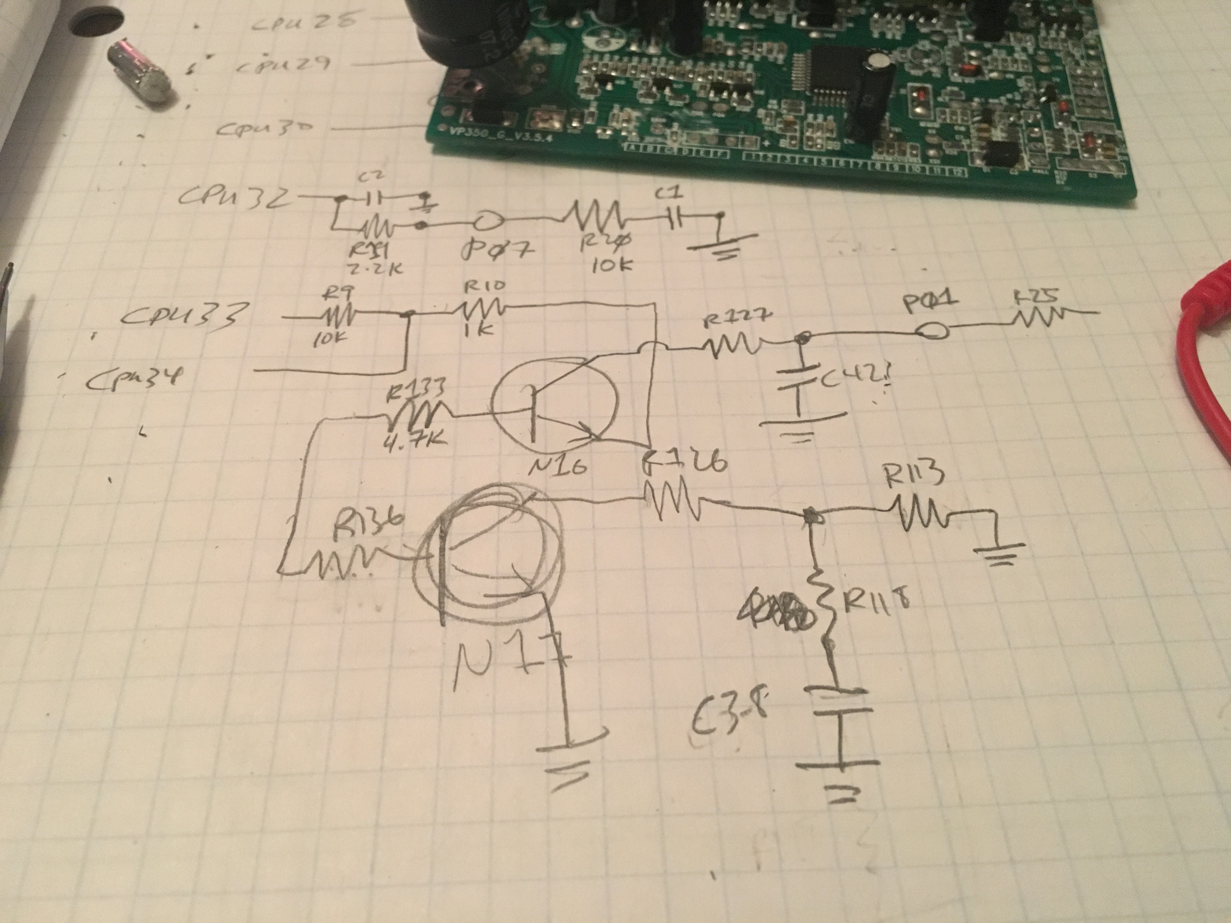
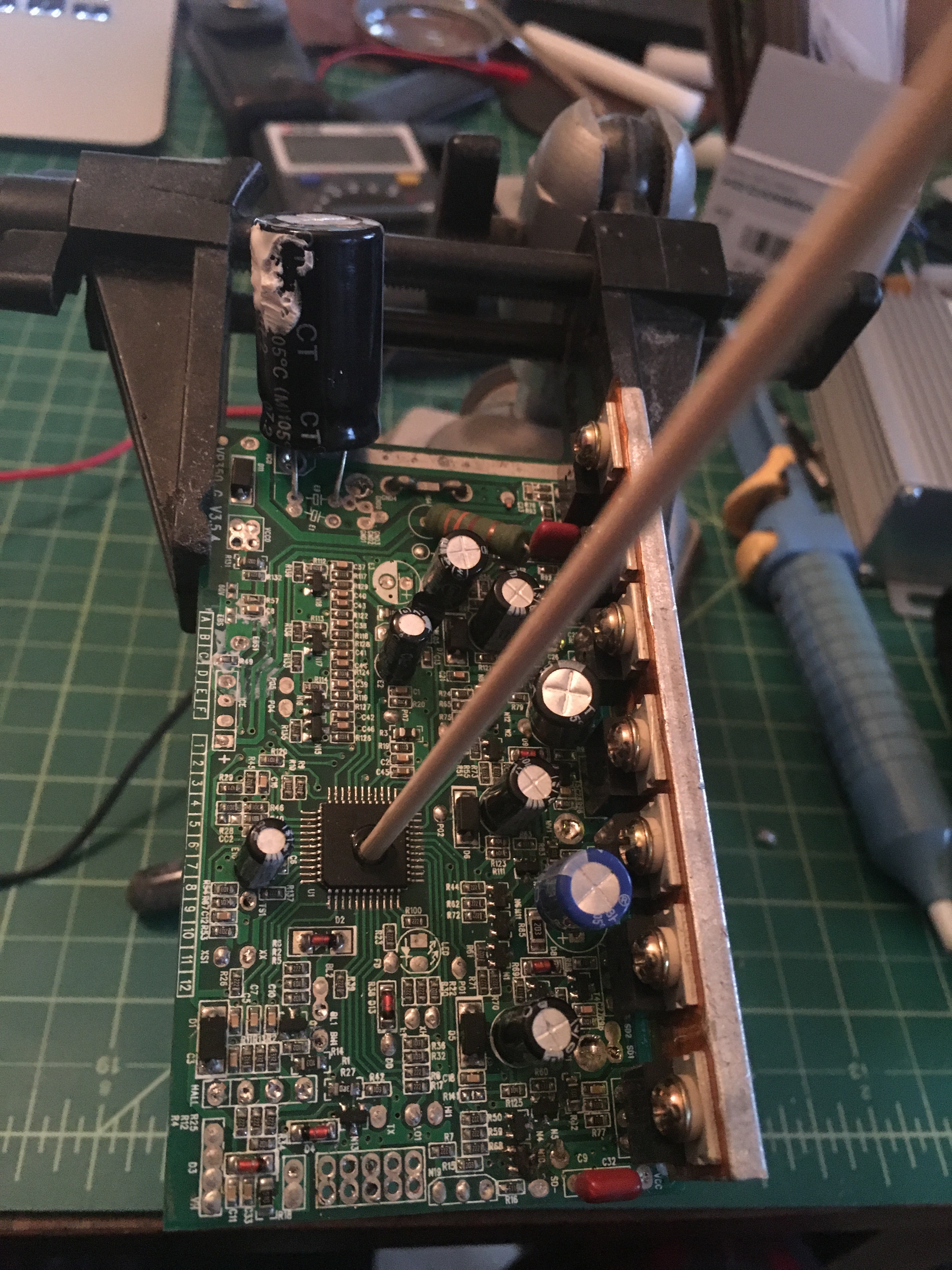
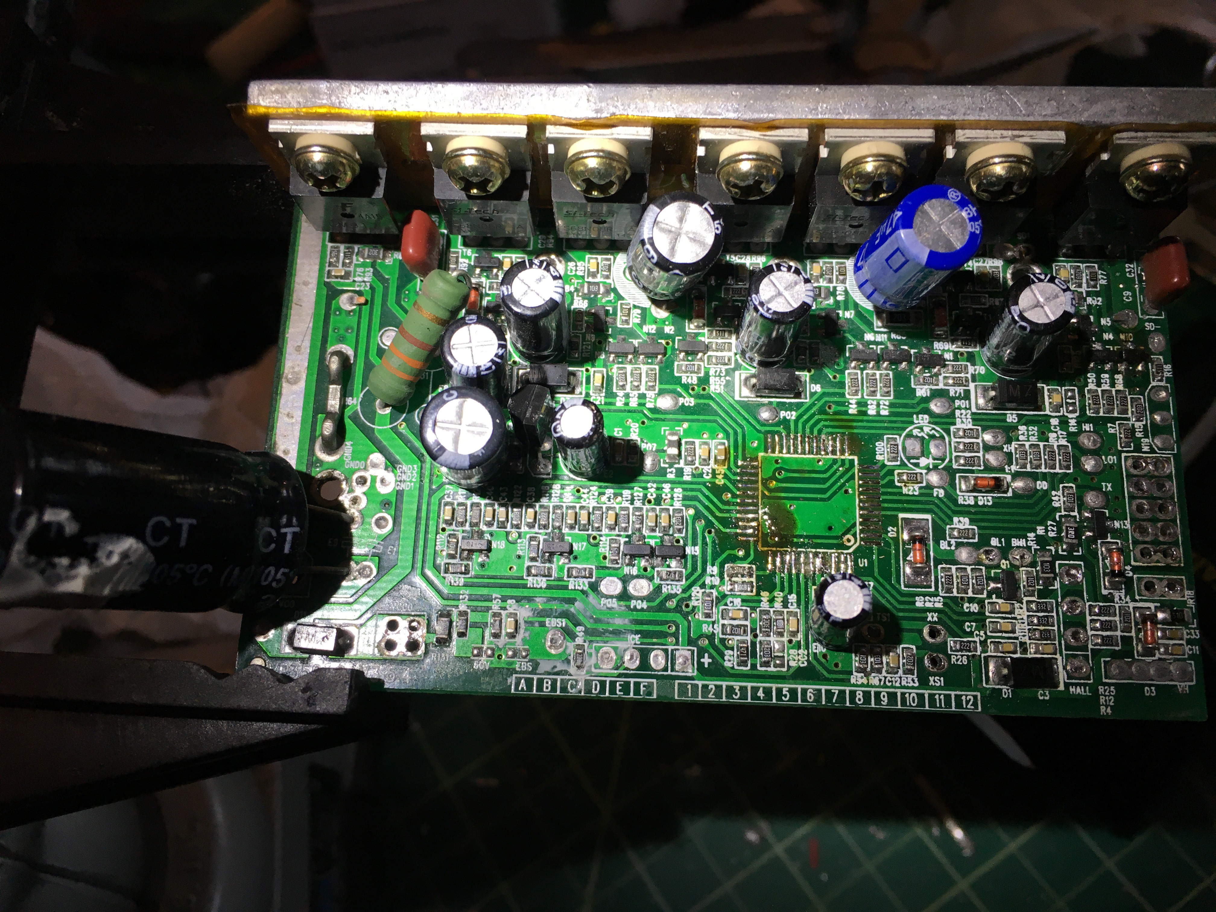
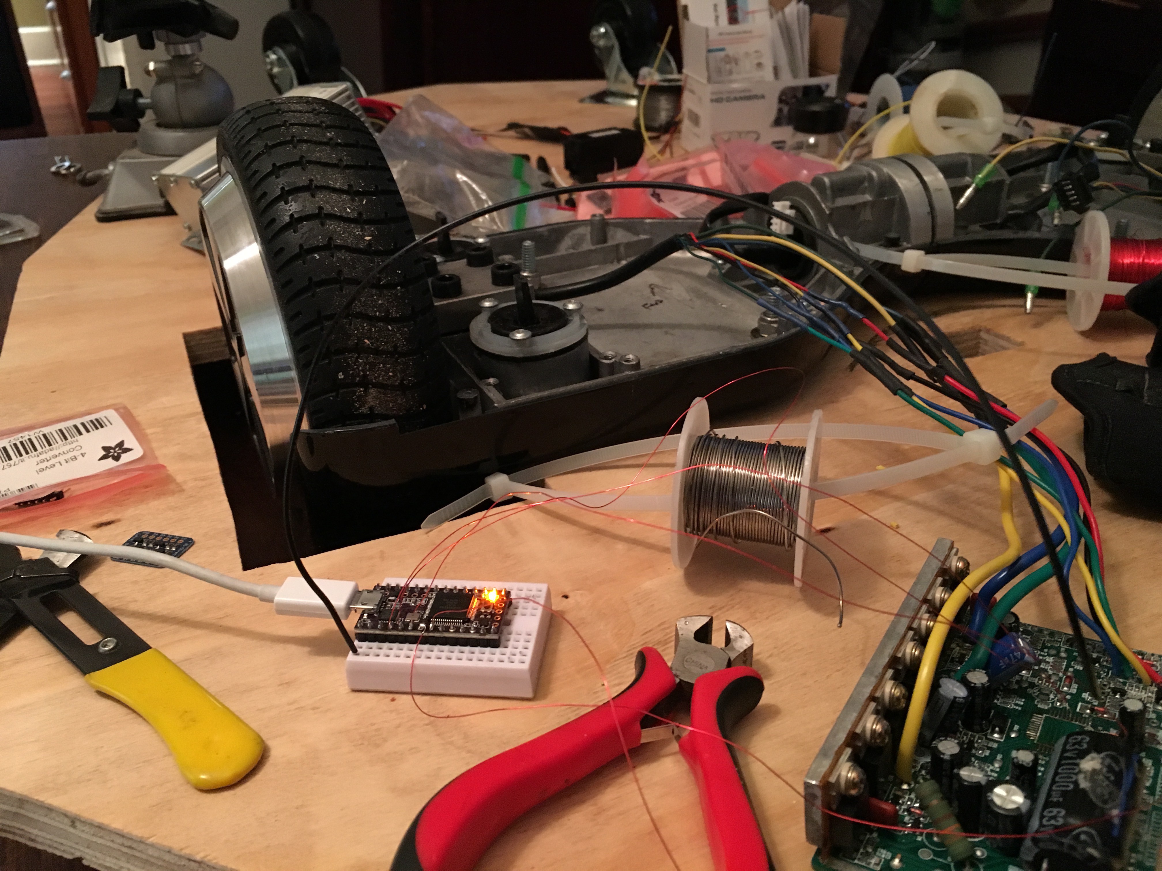
Reverse Engineering: Brushless DC Motor Controller
With a pile of BLDC controllers lying around, and none that do exactly what I want: better to re-use the parts than start over from scratch!
 Jorj Bauer
Become a Hackaday.io member
Already have an account? Log in.
Just one more thing
To make the experience fit your profile, pick a username and tell us what interests you.
Pick an awesome username
hackaday.io/
Your profile's URL: hackaday.io/username. Max 25 alphanumeric characters.
Pick a few interests
Projects that share your interests
People that share your interests


 Jrsphoto

 Scott Duckworth
 Jim Heising
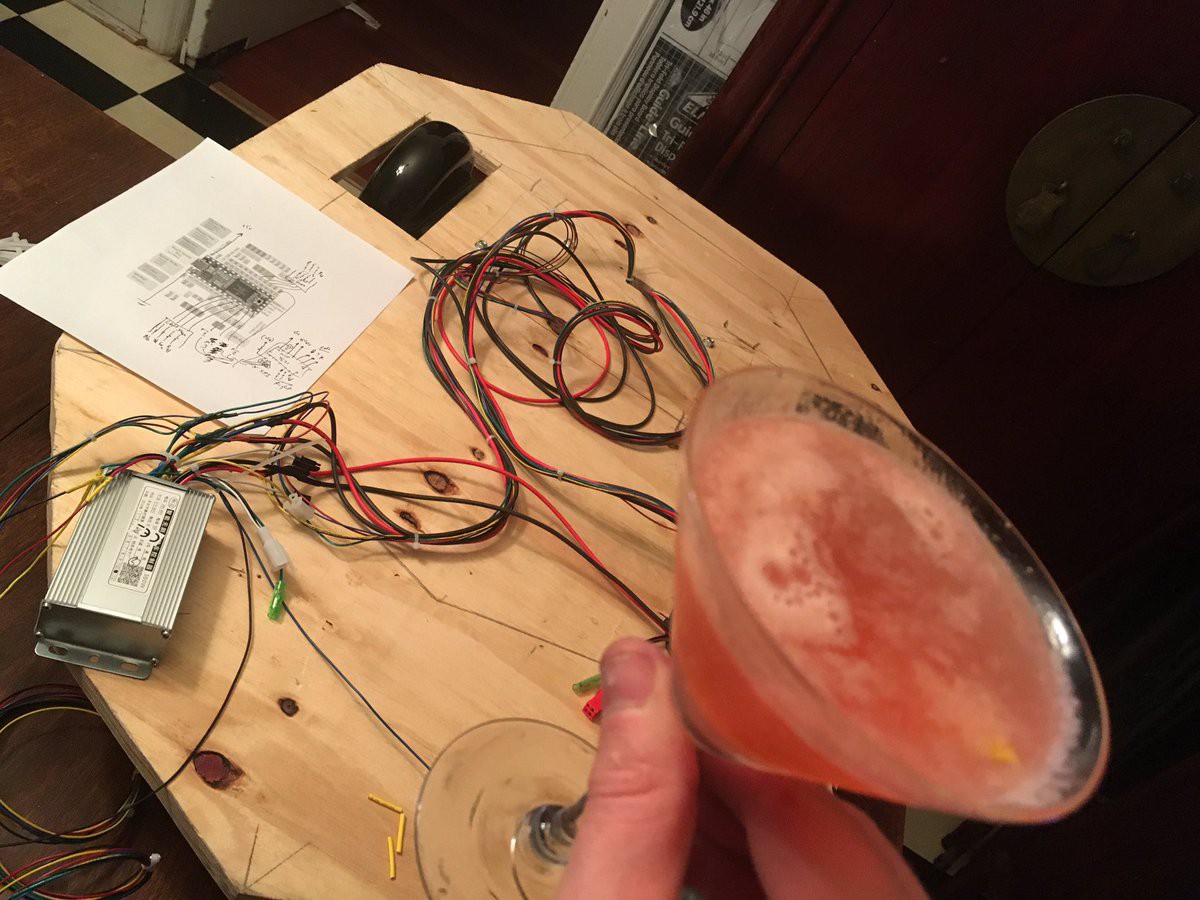
LOL! Don't drink and solder. And don't drink and code, however less fatal :D
I'm working on a speed pedelec, 500W on 36V, looking for some usefull info. Your blog is at least very recognisable!, thnx!