Theoretical results for error calculation, now with measurements!
I made 2 prototypes and measured the output voltage of both prototypes. The results are shown below.
Ambient temperature during measurements: 24°C
Supply voltage: 9.99V
Voltmeter used: Brymen BM857a
| Prototype #1 | |||
| set value [V] | measured value [V] | error [mV] | error [%] |
| 0 | 0.03528 | 35.28 | --- |
| 0.15 | 0.15125 | 1.25 | 0.833 |
| 1.34 | 1.34085 | 0.85 | 0.063 |
| 1.79 | 1.79069 | 0.69 | 0.039 |
| 2.12 | 2.12023 | 0.23 | 0.011 |
| 3.12 | 3.11964 | -0.36 | -0.012 |
| 3.77 | 3.76934 | -0.66 | -0.018 |
| 4.33 | 4.32833 | -1.67 | -0.039 |
| 4.85 | 4.8478 | -2.20 | -0.045 |
| 5.25 | 5.2482 | -1.80 | -0.034 |
| 6.49 | 6.4867 | -3.30 | -0.051 |
| 6.95 | 6.9462 | -3.80 | -0.055 |
| 7.28 | 7.276 | -4.00 | -0.055 |
| 8.28 | 8.2811 | 1.10 | 0.013 |
| 8.66 | 8.661 | 1.00 | 0.012 |
| Prototype #2 | |||
| set value [V] | measured value [V] | error [mV] | error [%] |
| 0 | 0.00339 | 3.39 | --- |
| 0.15 | 0.14943 | -0.57 | -0.380 |
| 1.34 | 1.33838 | -1.62 | -0.121 |
| 1.79 | 1.78795 | -2.05 | -0.115 |
| 2.12 | 2.11742 | -2.58 | -0.122 |
| 3.12 | 3.1162 | -3.80 | -0.122 |
| 3.77 | 3.76559 | -4.41 | -0.117 |
| 4.33 | 4.3237 | -6.30 | -0.145 |
| 4.85 | 4.8431 | -6.90 | -0.142 |
| 5.25 | 5.2427 | -7.30 | -0.139 |
| 6.49 | 6.4809 | -9.10 | -0.140 |
| 6.95 | 6.9405 | -9.50 | -0.137 |
| 7.28 | 7.27 | -10.00 | -0.137 |
| 8.28 | 8.27 | -10.00 | -0.121 |
| 8.66 | 8.6495 | -10.50 | -0.121 |
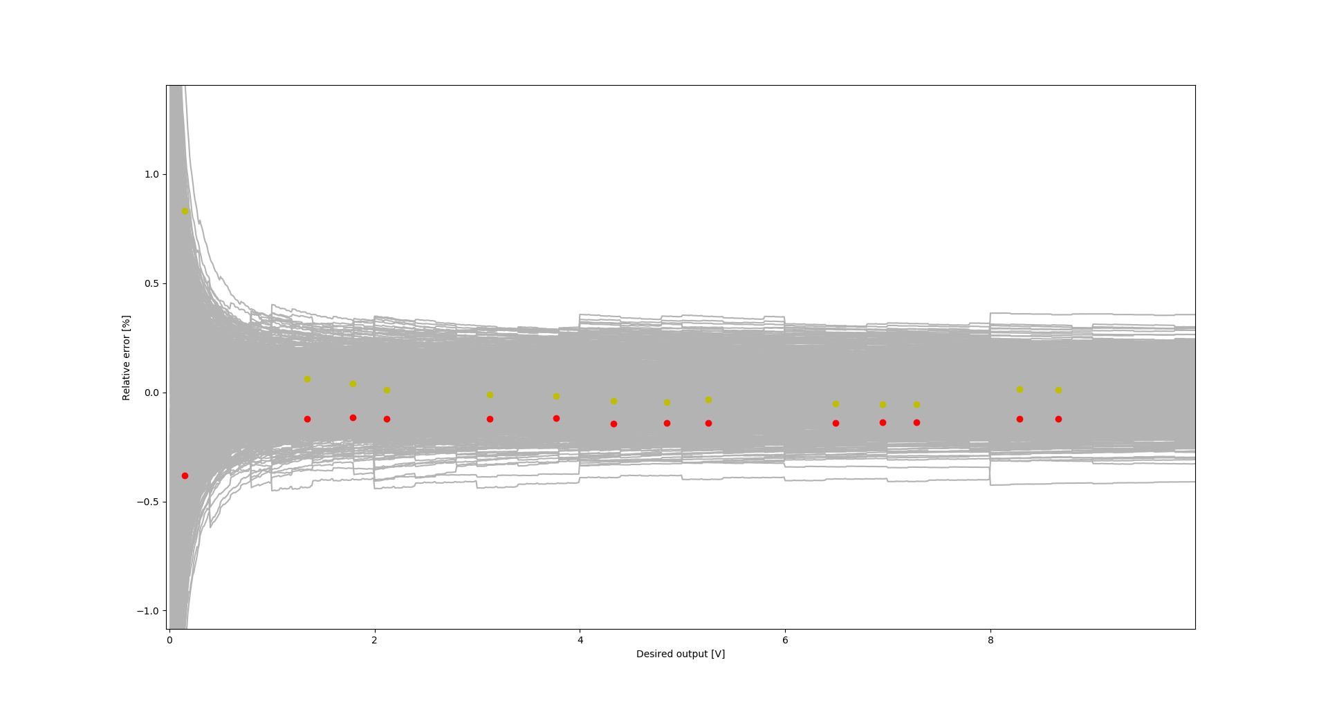
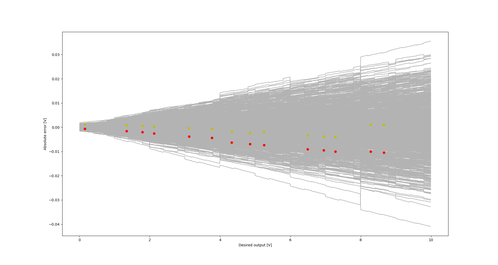
As can be seen, the measurements lie within the limits indicated by the simulation.
Discussions
Become a Hackaday.io Member
Create an account to leave a comment. Already have an account? Log In.