Mateus Abreu
NOTE: This project is gradually improving. It is fully functional at this point, but it could be better.
Consider:
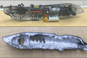
The car model is simplified in a box shape with zero forward speed. A gimbal is attached to the bodywork, so the vehicle and gyroscope are considered to be two separate rigid bodies which are dynamically limited. In addition, only the rolling motion in the YZ plane is considered and the rotational speed of the flywheel remains constant, see figure below.
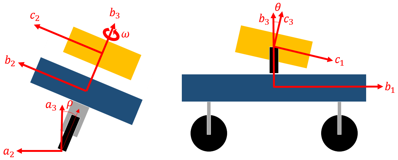
- a-Frame: Fixed earth inertial reference frame;
- b-Frame: Fixed to vehicle body;
- c-Frame: Fixed with the case of the Gyroscope Control (CMG)
- rho: rolling angle of the b-frame to axis 1 towards a-Frame (degree);
- theta: Tilt angle of CMG c-Frame to axis 2 for Frame b (degrees);
- omega: The rotation speed of the CMG wheel (RPM).
Paradigm:
The equation of motion in the coil is derived as a nonlinear quadratic differential equation, which states all the torus points on the means about the rho axis. To the left is an inertial term due to the mass of the bike and gyroscope, which is the acceleration perpendicular to the moment of inertia. The first term on the right is the Coriolis term as it relates to the product of two prices and. These terms arise when working with systems with multiple rotating reference frames. The second term is torque that must be generated by a gyroscope and the last term represents the wheel moment due to gravity.

Once an equation describing the system was obtained, the model was then tested using a computer simulation method. First, the system is described as a state space x * = Ax + Bu:
And it's linearized in the vertical position, which means rho * = theta * = rho = 0
Control:
After determining all the physical parameters and response rates, with the help of the state space form, the control gain K is calculated from the linear approximation model using Ackermann's formula. (in MATLAB the function name is Acker) is a solution that allows for method polar assignment. Polarization, is a method for modulating the poles of a given system by adjusting the gain of feedback from state variables.
The gain K is the PD controller for calculating the pre-speculative angular speed (theta *):

The controller achieves K ensuring the engine produces the torque needed to tilt the gyroscope and thus holds the car flexibly stable.
Signal Processing:
To estimate the vehicle angle, a low pss filter with a cutoff frequency of 2Hz was used in the acceleration data obtained at X, Y, and Z by the 250Hz split function:
The filtered acceleration is then converted to the absolute angle by the equation:
The passing moving average is 50 samples and the angular velocity derived from the gyroscope passing through the moving average is 35 samples.
Since the actuator input is angular and the control input counts as angular acceleration, the control must be integrated to actually work on systems with the MG90S.
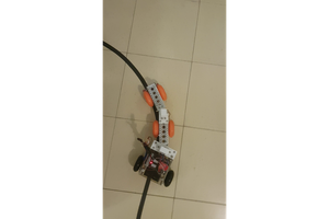
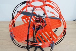
Prototype demonstration:
 Benjamin Prescher
 ken.do