I attended a Intel Arduino 101 Hack Night on 12/16/2016 at fat cat Fab Lab in NYC. Teams of participants assembled Robot Rover's as described here. The method for controlling the Robot Rover is tedious and requires a laptop keyboard. For demonstration purposes and to test the rover to insure it is functioning it is a useful set-up and thanks to the author for a great write-up.
I decided to buy parts to build my own rover. There are a wide variety to kits available. I chose one with a metal frame and big tires. I decided to power the motors initially with alkaline batteries and the Arduino with a Anker Powercore Mini lipstick recharger. After getting it assembled and running I began to search for other ways to remotely operate it. I came across a couple of descriptions such as this one featuring nRF Connect application from Nordic Semiconductor , this one describing a phone app called Blynk and this one from Electron Hacks . After exploring these possibilities I decided to pursue using Blynk as it seemed to be a more straight forward (easier) approach.
Install Blynk on your mobile phone device. The website has all of the instructions in the documents section. After installing the app on your phone Blynk will issue an Auth Token that will give your device a unique address. This token needs to be inserted into the sketch on line 39. You also need to install the Blynk library as well as the Adafruit Motor/Stepper/Servo Shield Library in your Arduino folder. You may also need to install the CurieBLE library if this is the first time you are using the Arduino 101 controller (Arduino>Sketch>Include Library>Manage Libraries>CurieBLE).
I initially set up the app using push-buttons for rover directional movement and a slider for motor speed for motor speed. (this solution was inspired by Intel Arduino 101 BLE Blynk Tank posted on Electron Hacks Thanks!) The sketch for this version is here.
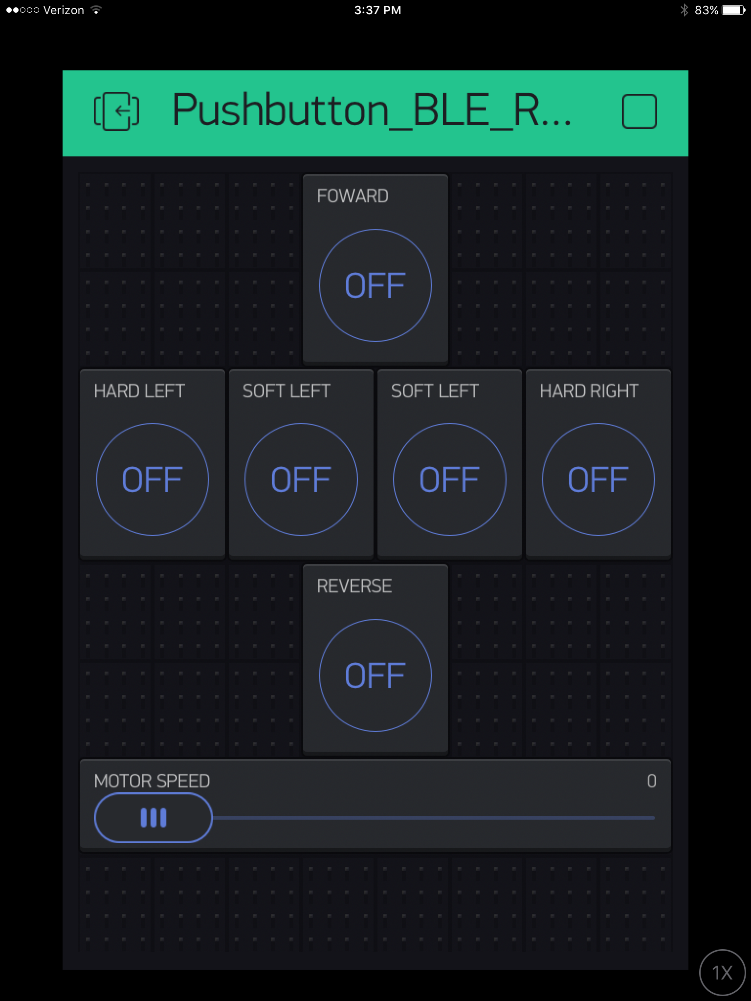


While setting this up I noticed a joystick widget and decided to try and code a solution to it. After getting frustrated I decided to look around for some help. SparkFun provides a code example for its hardware joystick that is very clever and straightforward.


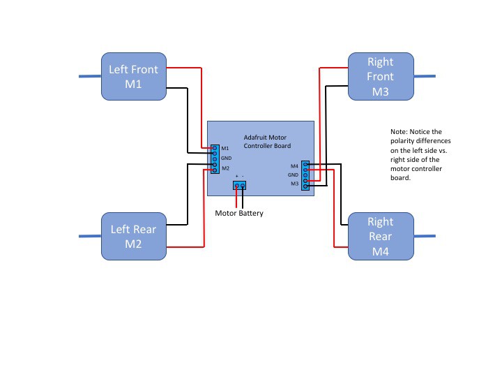
It assumes there are eight directions of travel for the joystick to designate. It translates the joystick movement into a Rover direction as follows. The Blynk joystick widget travels along an x and y axis that are 255 units in length, making the midpoints 128. The direction of the joystick movement can be determined by comparing the joystick x and y value to 128. If x is less than 128 (left relative to the center) it is assigned a value of -1. If it is greater than 128 (right relative to the center) it is assigned a value of +1. If equal to 128 (centered) it is assigned a value of 0. The same is done for the joystick y axis values. For example when x>218 and y>218 the x-direction is 1 and the y-direction is 1 making the joystick in the forward right area. The sketch takes the x and y direction combinations listed in the Fig. 2 Joystick Direction Table powers the appropriate motors to steer the Rover. Note that the Rover steers in the direction of the unpowered motors.
The SparkFun example employs another clever strategy. Apparently the SparkFun joystick does not always return to its exact center. To correct for this a "threshold" area around the center point is created. This comes in handy for the Blynk joystick as well. While the Blynk joystick always returns to the center (see the Auto-Return switch in the joystick set-up) the joystick creates thousands of x,y combinations. This can make the Rover motion erratic if the x,y values are compared to 128 to determine a direction. I found that creating a threshold area around the center of +/- 20 for the x and y values works well.
The sketch powers all four motors in the same direction for forward and in the opposite direction for reverse. For a left turn the left front and rear motors are unpowered (RELEASE)....
Read more »
 Films4You
 Esmacat
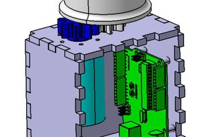
 Kyle Rector
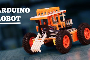
 M TECH IDEAS