 Evangelos Petrongonas
Happy new Year Everybody, welcome to this 2nd DesBlog. Today we will talk about the Analog Stage, which is the Output Stage of our Wave Generator.
Before we begin analysing the circuit let's take a look at the IC's we are going to use.
- OpAmps. Well... pretty much the most important decision for the Analog Part of the frequency is the OpAmps that will be used. They need to be
- Rail to Rail I/O so that we can use most of the -limited- voltage selection that we have in our disposal.
- Very Low Power. Do you remember the negative Power Supply that we designed last time. It had the limitation of low current output, it would drop to around -4.75 V, when drawing 5 mA of current . In order to avoid that issue, the supply output current should be kept to a minimum.
- High Gain Bandwidth Product. GBP, usually specifies the maximum frequency that the OpAmp will retain it's unity Gain. If the max frequency is exceeded, then the Op Amp will output a smaller, in terms of Vpp, signal. To overcome that obstacle, a high GBP is required
- Fast Slew Rate. SR is an indication of how quickly the output of the OpAmp can change and is measured in V/μs. A higher frequency signal, will transition faster from Voltage A to Voltage B and the Op Amp must follow the pace. If it lags behind the the Signal will be distorted. For the particular application an SR higher than 10 V/μs is sufficient.
- Low Cost . As everything else in this project budget is an issue.
And the winner is................
LM6142 !!!! http://www.ti.com/product/LM6142
LM6142 is a Dual Op Amp from TI which, pretty much fulfills most of our needs.
it has a Rail to Rail output swing of +- 4.995 V, low supply current 650μΑ/ per amplifier, slew rate of 5-30 V/μs and Unity Gain around 5 Mhz. if you also consider that is relatively low cost it's a perfect IC.
- Digital Potentiometer. Not much to cover for the digital Pot. It will be used to determine the Amplitude and Offset of the output Signal. A 10k 8bit low cost Potentiometer is all that is needed. The reason that a digital pot is used instead of an analog one, is because the Amplitude and Offset adjustments will be done through software ooohhhhh.
The ic that was selected is the MCP42010 from Microchip http://www.microchip.com/wwwproducts/en/MCP42010
Beware though that in the future it might change from the 2 channel to 3 channel variant, depending on the Digital Stage Design.
Now we are ready to discuss the circuit itself.
And voila :
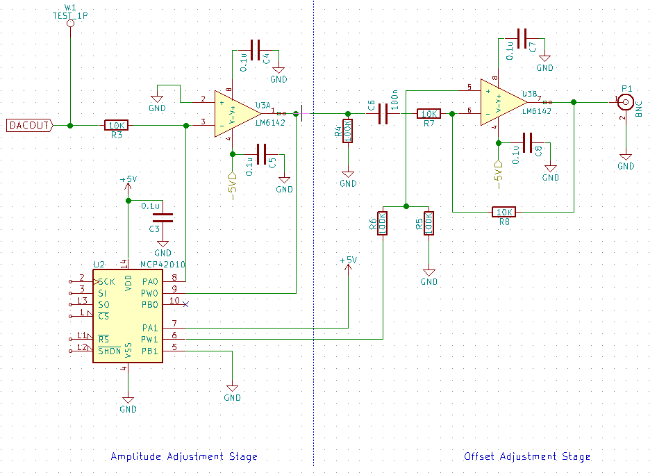
Hopefully is not very complicated and the more experienced hackers out there will understand it in a blink of eye.
The output DAC is feeded into the Inverting Input and the first Op Amp is in a simple Inverting Configuration. The output is ,where Po is the first channel of the Digital Potentiometer.
Since the maximum Pot Resistance is 10K and R3 is also 10K the max gain of the opamp is 1. As a result the amplitude resolution is expected to be around 15-20 mVpp, depending on the Dac Output Voltage (More on that in the next DesBlog.)
The signal however is dc biased, as the dac output is positive. In order to remove the dc bias, a coupling capacitor is connected in series with the next opamp. In addition a high value resistor is used, to avoid dc current block. The capacitor and the resistor combined is a Low- Pass Passive Filter. Now that the signal swings around Ground (0), a Dc offset can be easily implemented using one more opamp. Ideally it would be configured in a Voltage follower-buffer configuration, but the fact is,the input signal is inverted, and it would remain inverted. For this reason a Differential Amplification topology is used. The output ,according to the following equation, is :
,where V1 is the output of the previous OpAmps and V2 is the Voltage offset which is created by the second channel of the Digital Potentiometer which acts as a Voltage Divider. The above equation for the given resistor values equals to
That way we can now configure both the Amplitude and the DC offset.
One last note though, since the accuracy of the resistors is an issue, as even slight variations will change the gain, high precision resistors are highly recommended. Personally i will be using 0.1 % resistors as i believe it is the sweet spot between cost and accuracy for this application
As always i'll be more than happy to hear your ideas and suggestions :)
See you Soon and Happy New Year. :) :)
Discussions
Become a Hackaday.io Member
Create an account to leave a comment. Already have an account? Log In.