 Evangelos Petrongonas
Hello and welcome to the 1st Design Log or DesLog. Every now and then new logs will be uploaded, in order to keep you informed and suggest new ideas for the project.
For this first DesLog we will take a look in the Design of the Negative Power Supply for the Output Operational Amplifier. This stage is quite crucial in order to determine the output specs of the Waveform Generator. The output current is limited in order to maintain -5V without too much deviation. After the first two unsuccessful attempts, a final design may, fingers crossed, be ready. The failed attempts are the following :
1st Attempt:
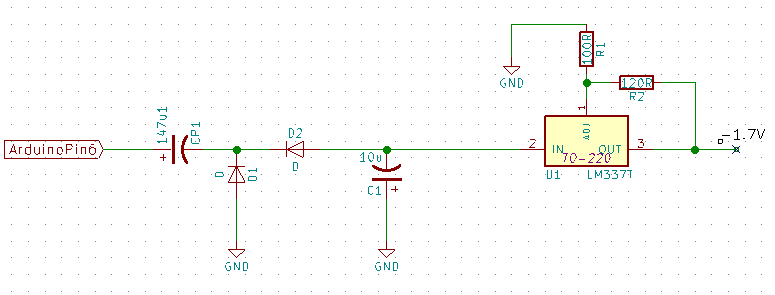
The Arduino was used in order to produce a 50 % DC pulse and then it was kind-of rectified so to create negative voltage, then signal was fed to an LM337T Negative Voltage Regulator. The problem was apparently that the the voltage after the rectification wasn't high enough and the regulator wasn't working. Moreover this method utilized the Arduino to create the oscillation (about 100KHz) required by the circuit to operate. As a result this design was abandoned. (The circuit described above is visible in the figure below)
2nd Attempt:
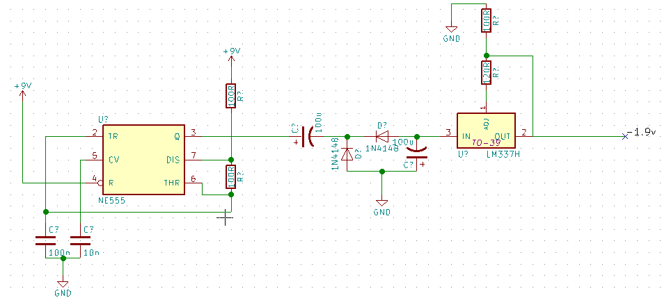
The natural way forward was to increase the voltage in the Rectification Circuit. In order to do so, instead of creating the oscillation from the Arduino, a simple NE555 timer IC was used to take its place. An extra benefit of that approach was that the Arduino code was no longer needed to produce the pulse, saving up valuable RAM space and processing time. This attempt though had, a huge downside, the fact that it required an external 9V Power supply, which was not in line with the project's main concept.
3rd Attempt
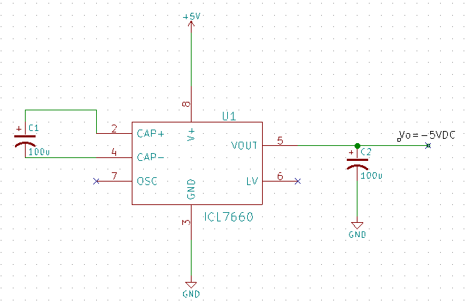
Back to the drawing board for take three. This time a specialized IC (ICL7066) was used to both invert the 5 V input and produce -5V, as well as regulate it. The IC uses the same method as described in Attempt 2, but with much higher power efficiency (~95%). Unfortunately that translates into slightly higher cost for the final product. Another disadvantage is the fact that the voltage is regulated for an output current of around 10 mA which is not as high as it was initially designed. That limitation however, is acceptable , as most Waveform Generators are used with HiZ loads (in this case more ta 1Kohm input impedance).
Finally further testing will take place wth the MAX680 IC, which claims even better power efficiency, but it will have to wait for a future DesLog
I hope you enjoyed this first DesLog and i'll be more than happy to see your thoughts and suggestions
See you soon :)
Discussions
Become a Hackaday.io Member
Create an account to leave a comment. Already have an account? Log In.