0%
0%
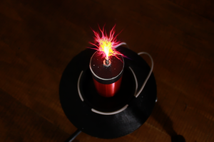
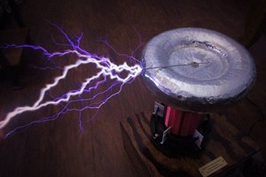
Tesla Coil - Scientific way
There are a lot of information about Tesla coils, but still it's tricky to build/tune one. Here we would like to go over and explain ...
Become a Hackaday.io member
Already have an account? Log in.
Just one more thing
To make the experience fit your profile, pick a username and tell us what interests you.
Pick an awesome username
hackaday.io/
Your profile's URL: hackaday.io/username. Max 25 alphanumeric characters.
Pick a few interests
Projects that share your interests
People that share your interests
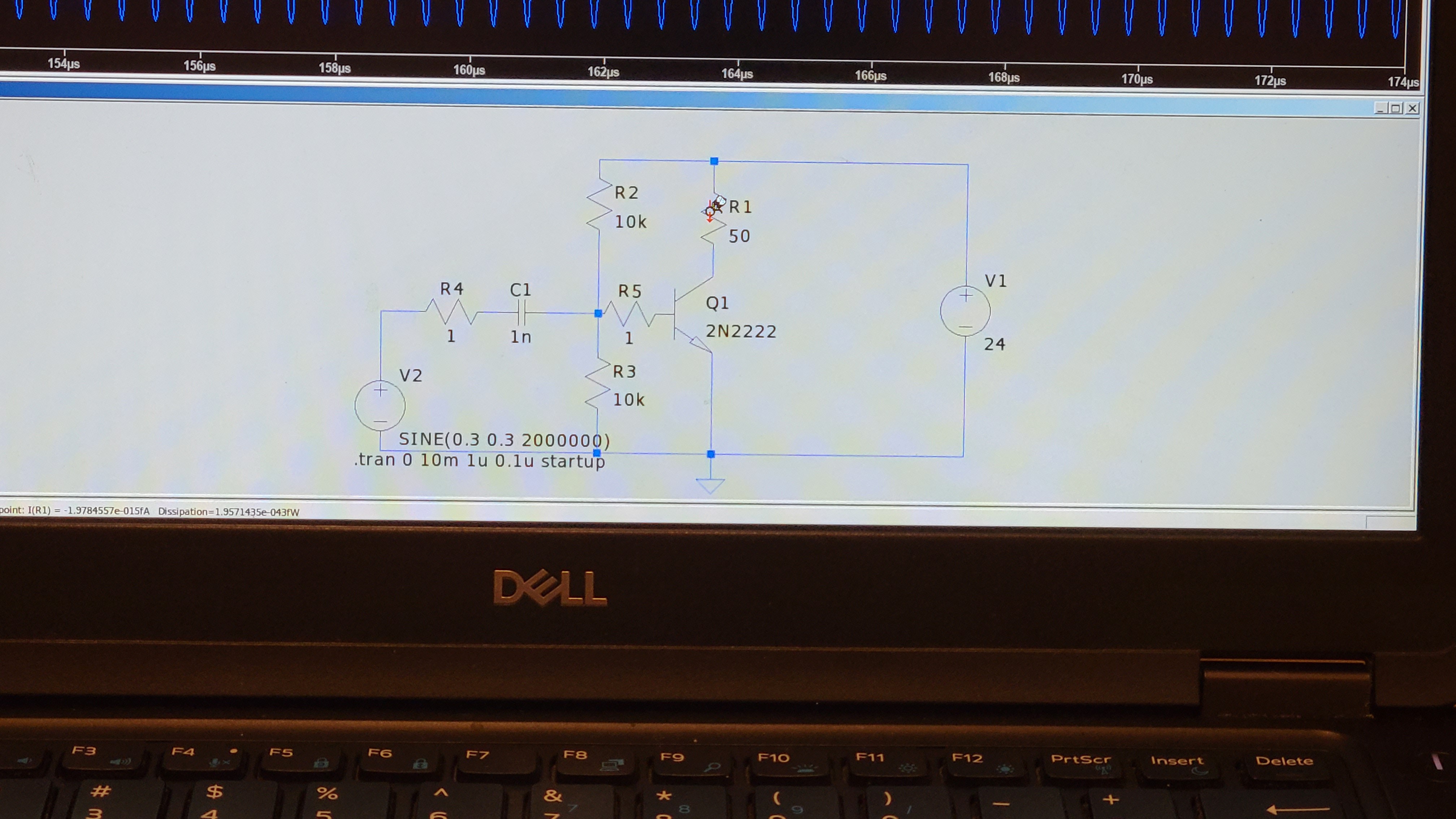
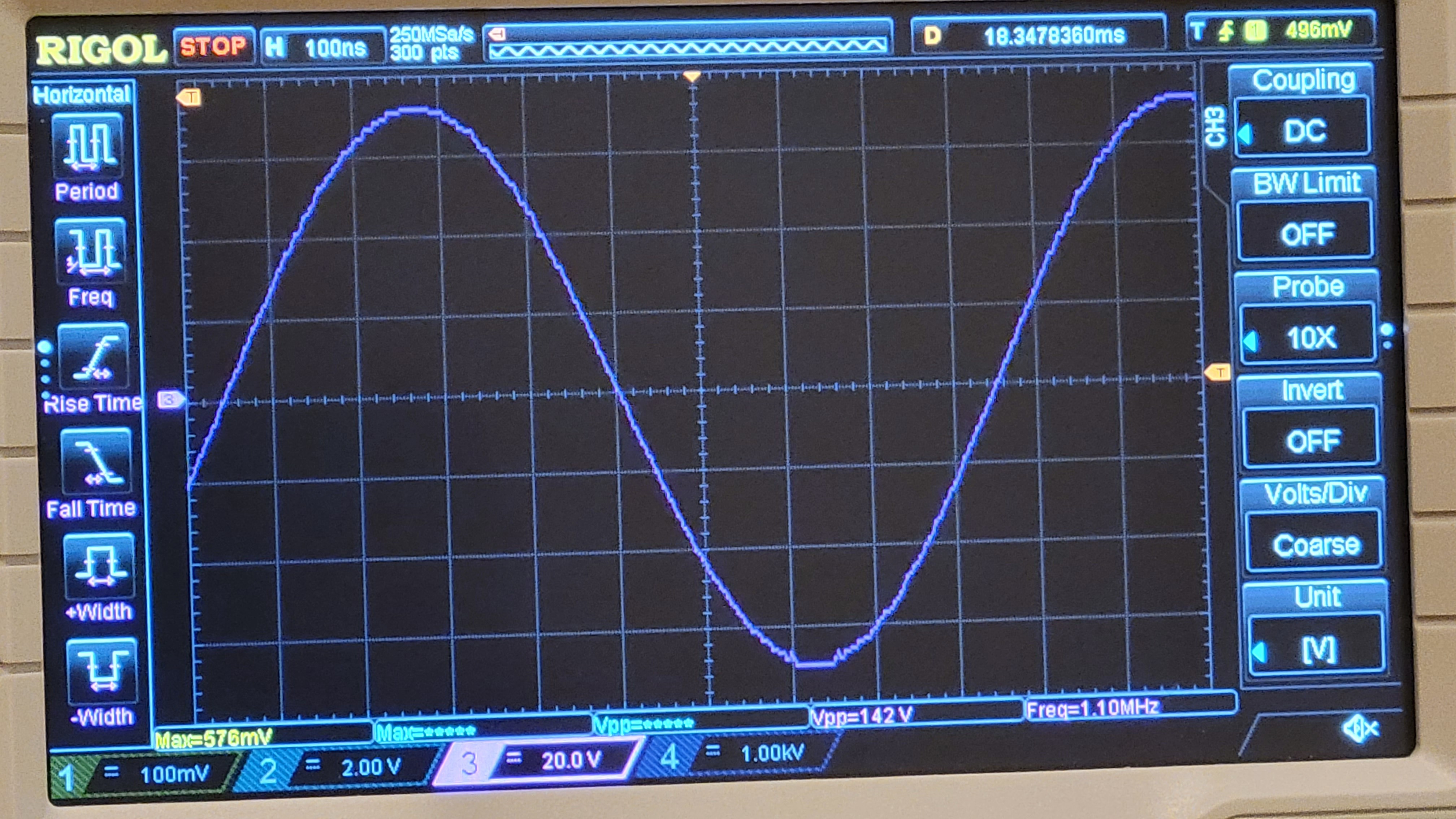
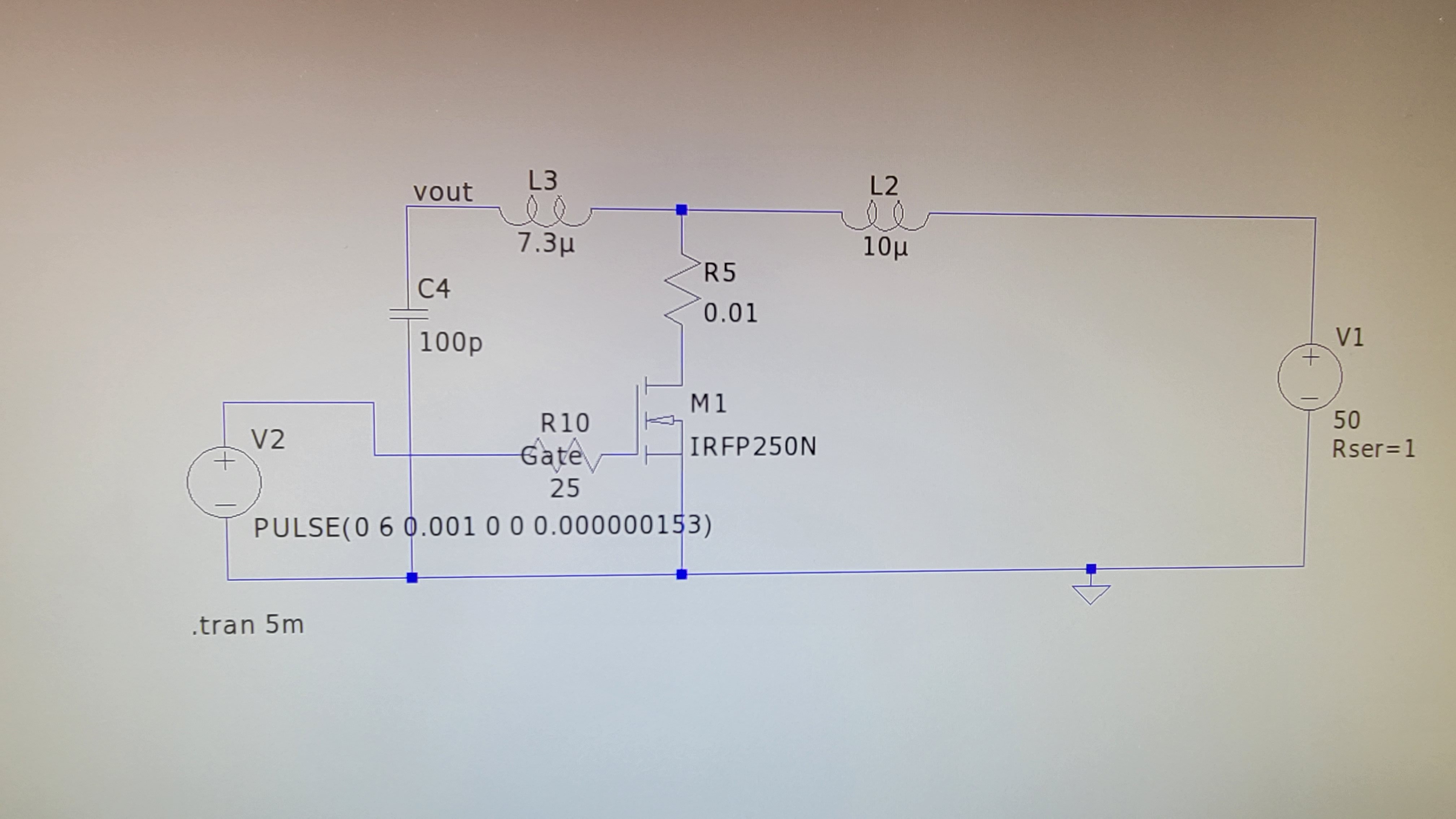
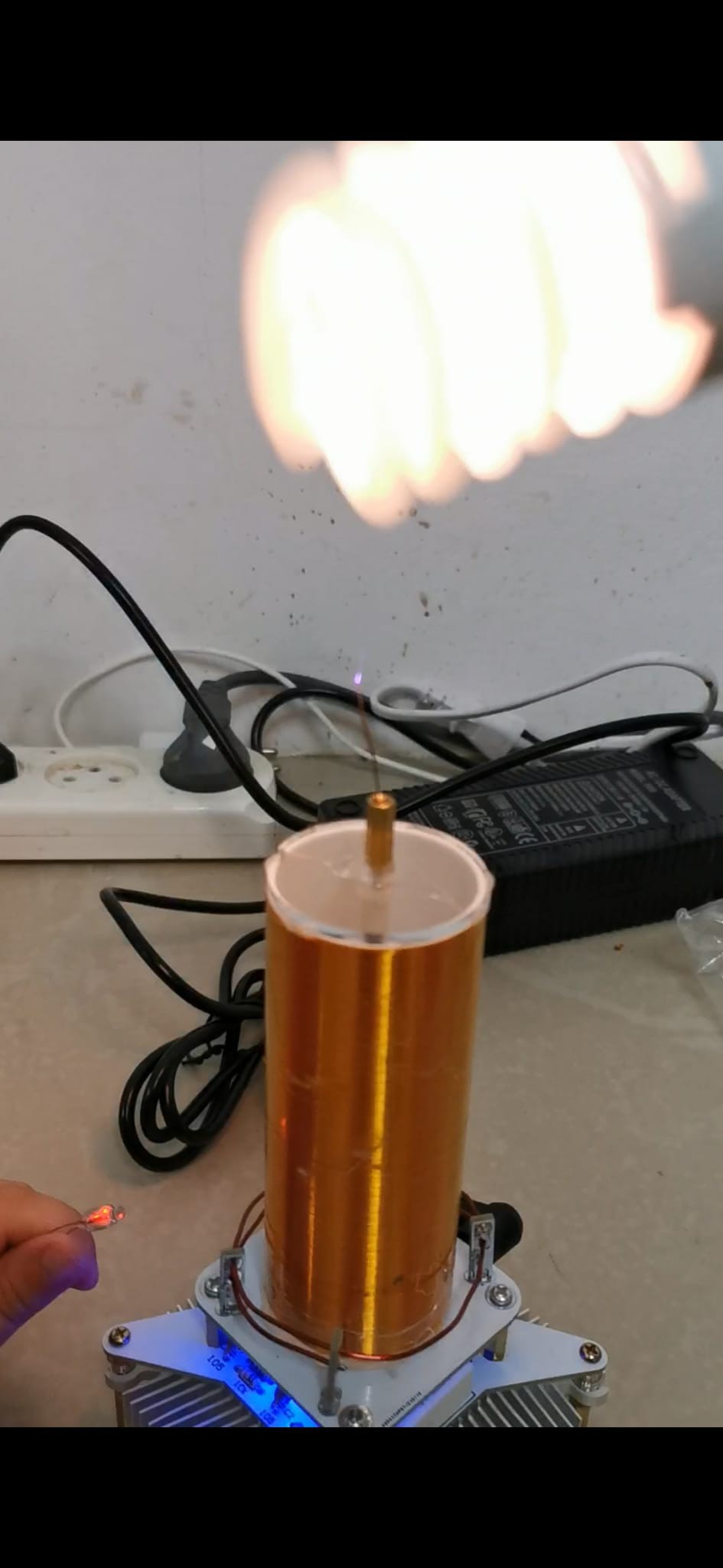
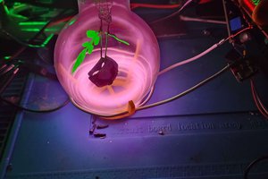
 After careful examination I found that this Tesla coil had the same schematic like the one I saw on 'Youtube Plasma Candle' but with different frequency and different MOSFET. After being extremely optimistic I found out that this device didn't give me much insight. Although I know which MOSFET is used (IRFP250N) and coil values for the device, connecting scope to this device actually paralyzed it.
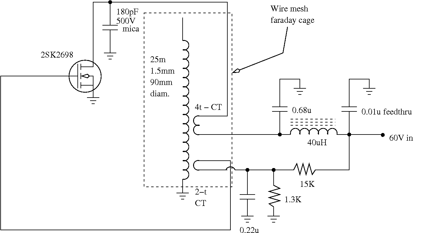
 Zach Armstrong
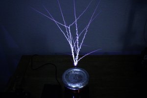
 YSPACE Labs