 shlonkin
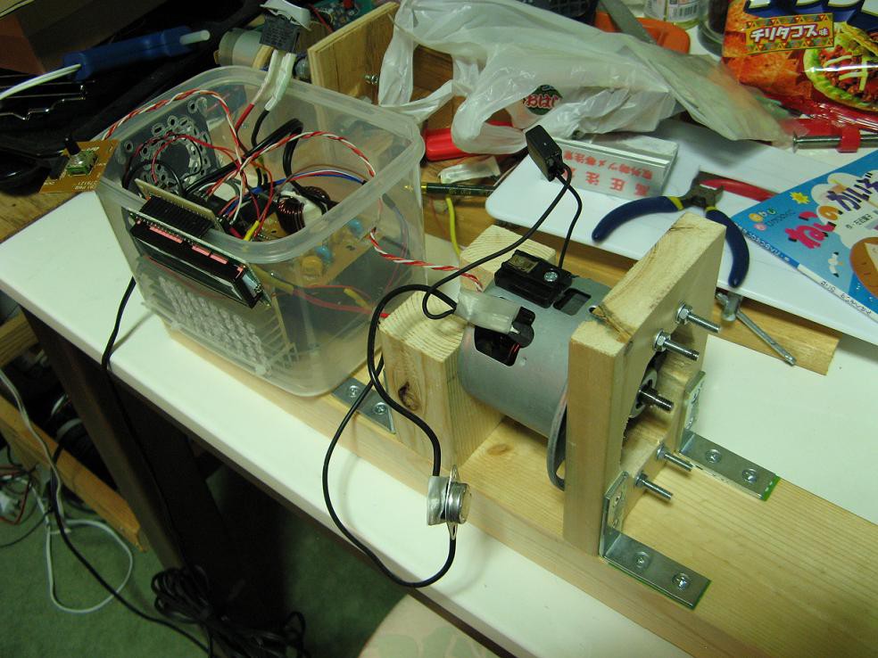
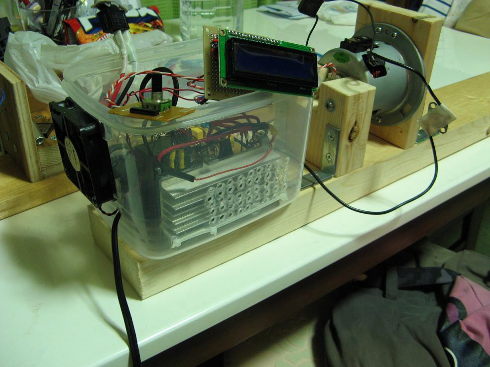
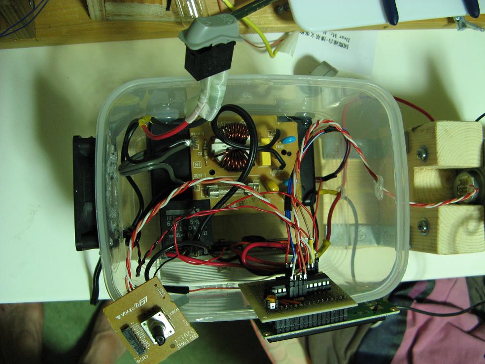
The motor is now attached to a 2x4 using some wood blocks and L brackets as you can see in the pictures. It feels really solid. Right behind the motor is the control box, which is a plastic food container from the 100 yen store. It is still far from complete, but functional. It will eventually have a control panel on the top, but at this point the controls and display are just hanging over the edge.
As for the tests, I first programmed it with some really basic debugging code and connected it to a small light bulb instead of the motor. It worked ok, but the bulb didn't seem to respond to the changes in pwm duty cycle as much as expected. Anyway, I finally got up the confidence to connect the motor and ZOOM! The IGBT failed in such a way that it was stuck on. The motor screamed like a jet engine for three seconds till I yanked the plug from the socket.
What exactly happened? I'm not sure, but some reading seems to suggest over voltage from the inductive load. I thought my flyback diodes would protect things, but maybe not. Also, the unresponsiveness to the duty cycle made me wonder if my IGBT driving was not good enough. Perhaps the gate resistance was too high to switch quickly. I was also driving it at about 2kHz, which may have been too fast considering the driving circuitry.
Try two: I replaced the IGBT with another salvaged from garbage, reduced the gate resistance, and added a 500V varistor across the motor(the IGBT is rated for 600V). Then I reduced the pwm frequency to about 240Hz. The light bulb test looked much much better, meaning that this way of driving was much more effective. Then I crossed my fingers and hooked up the motor. It worked beautifully!
Now to finish up the controls and turn this into a lathe.
Discussions
Become a Hackaday.io Member
Create an account to leave a comment. Already have an account? Log In.