 Enrico
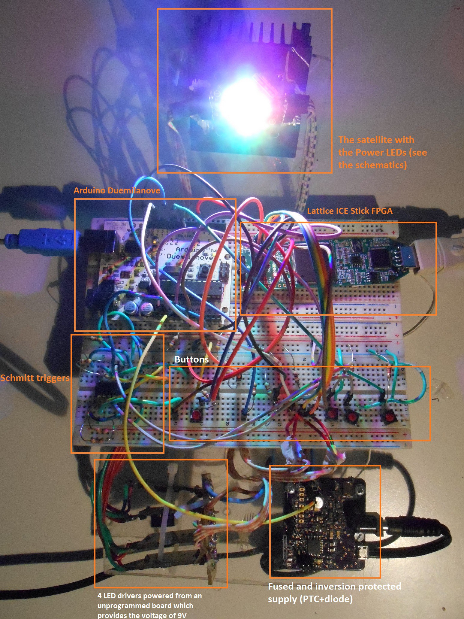
Since this project is all breadboarded, I will share the schematics (and pictures) since there is no a real layout, and Fritzing would became insanely complex. Below, a picture with the regions herein described through the schematics and the connections, just to make the wirings not too overwhelming:
Here you can see the iCE Stick FPGA used, and the highlighted in orange connector J2, and pin 1 highlighted too:
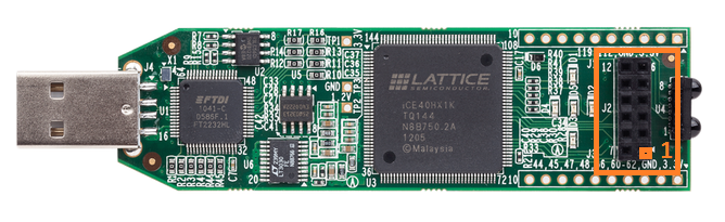
From here, I am referring to the FPGA connections as iCE Stick header J2 pin XX.
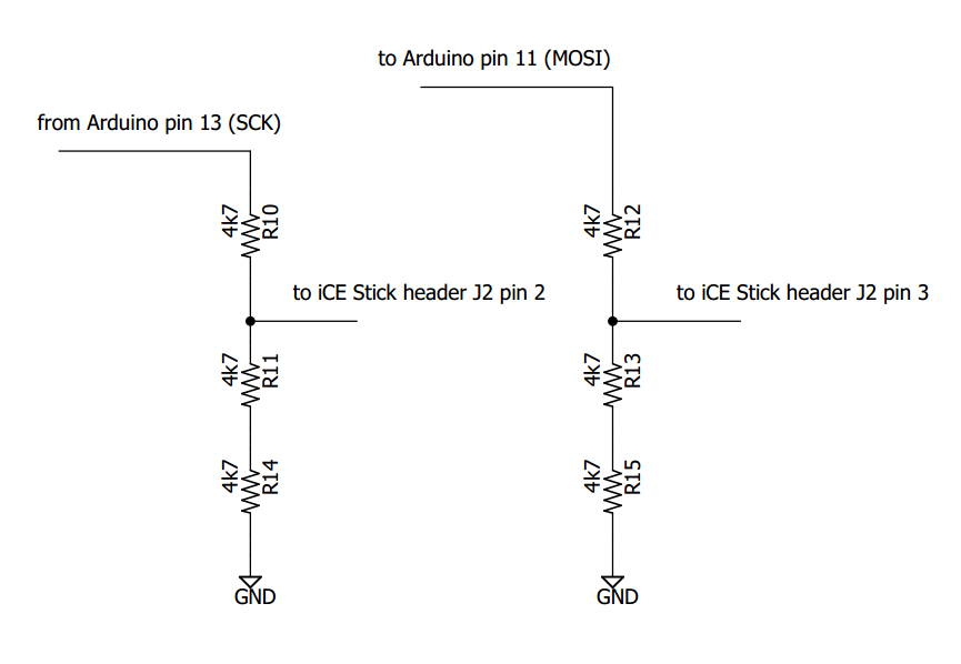
The communication between the Arduino and the FPGA happens through unilateral SPI communication, so that a simple 2/3 resistor voltage divider is sufficient to safely connecting the 3.3V FPGA to the 5V Atmega:
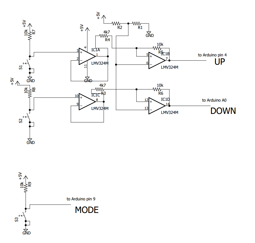
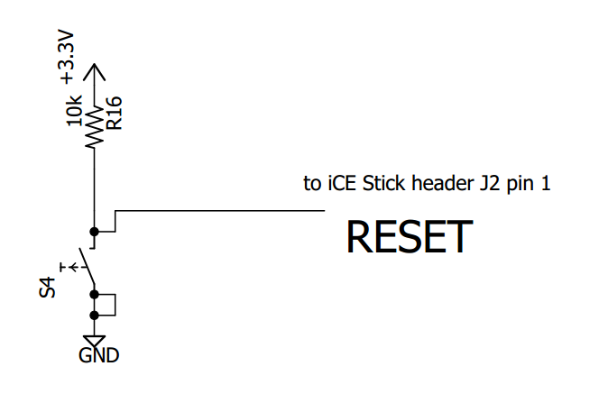
If needed, it is provided a RESET buttons to re-initialize the FPGA:
If you take the entire VHDL implementation "as is", for debugging purposes you will see the SCK pin redirected on ICE board LED D1, while the other 4 color signals are also duplicated on the remaining ICE debugging LEDs.
The output of the FPGA is feeding the power LEDs through a module that I've build few months ago, but you can power up anything else. Here you can see a picture of one module which can be fed with a PWM signal as high as the supply voltage, where such supply can be as high as 20V. As already said, you can connect any LED to try out the Arduino+FPGA setup.
Here is the module, powered at 9V, where the PWM swings between GND and 3.3V of the ICE Stick:
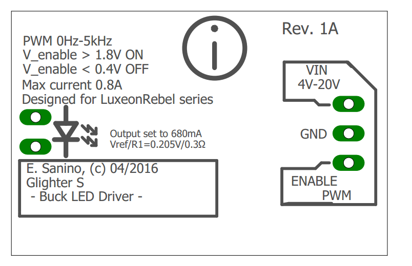
The LED connections is shown on the board too.
Here you can see the briefing of the entire connection setup within this log, where some of them are conditioned using the above schematics (all names are referred as in the schematics, so that you can reproduce the connections):
- RESET active low button S4 -> FPGA J2 pin 1
- Arduino pin 13 -> FPGA J2 pin 2
- Arduino pin 11 -> FPGA J2 pin 3
- One active low switch S1 -> Arduino pin 4
- One active low switch S2 -> Arduino pin Analog 0
- FPGA J2 pin 7 -> enable/PWM pin RED driver
- FPGA J2 pin 8 -> enable/PWM pin GREEN driver
- FPGA J2 pin 9 -> enable/PWM pin BLUE driver
- FPGA J2 pin 10 -> enable/PWM pin WHITE driver
Remember to keep the GND reference between Arduino, ICE Stick and all the 4 LED drivers in order to avoid fire. The 4 LED drivers are soldered on perfboard and a 4 wire strips is connected in J2 of the ICE Stick.
You can spot a second board, which provides power to the LEDs: it mounts a second Atmega which is not used. That board (a Lino board) was lying around and I decided to use it, since I am also late in the submission for the challenge. It provides only few basic electrical protections. :)
Discussions
Become a Hackaday.io Member
Create an account to leave a comment. Already have an account? Log In.