Close
0%
0%

Circadian - Radio control your internal clock!

A radio controlled melatonin saving lamp

Similar projects worth following
Our internal circadian rhythm clock is set by light and this lamp is radio controlled, making your internal clock radio controlled!

My goal for the 1kB Challenge was to come up with an idea that could become a new product in spite of the code size limit. A lamp that emits energizing bright white light during the day and fades to a mellow glow in the evening has been on my project list since a long time now. Philips and other companies are selling smart lamps with this functionality, but of course using bluetooth and an app.

The 1kB Challenge inspired me to realize this project using a DCF77 receiver. In contrast to the commercial version, this lamp synchronizes itself automatically. No app and no smartphone needed. Sometimes less is more.

A double click with the lightswitch overrides the melatonin saving mode. You know, for one of these nights before a deadline.

Lighting Concept

The development process of Circadian started with a lot of research considering melatonin, the circadian rhythm and light therapy and was followed by picking the LEDs. I decided for Osram's Oslon SSL series because of its high CRI (95) white and broad color variety. 12 neutral white LEDs provide 2100lm during the day and 2 yellow, 2 amber, 2 red and 2 hyper red LEDs emit an enchanting orange light at up to 1100lm. The LEDs are split up in two white strings and one orange string at 18V each.

In contrast to commercially available lamps, Circadian does not use a warm white LED for its evening mode, because even warm white has a lot of blue spectrum. Light containing only wavelength above 530nm does not suppress the production of melatonin and amber being the bluest of the LEDs I used lays in safe distance to this threshold. Another conclusion of my research was, that I should use the white light at full power in the morning to increase my serotonin level.

Design

After the emitters were chosen, I could start working on the appearance of the lamp. I decided for a minimalistic design, which seems to be held together by a continuous brushed aluminium rod. The rod is actually a 12mm tube press fit into the upper heat sink and then two screwable aluminium pieces attaching the diffusor plate to the lower heat sink. The raw brushed finish was achived by filing the turning parts.

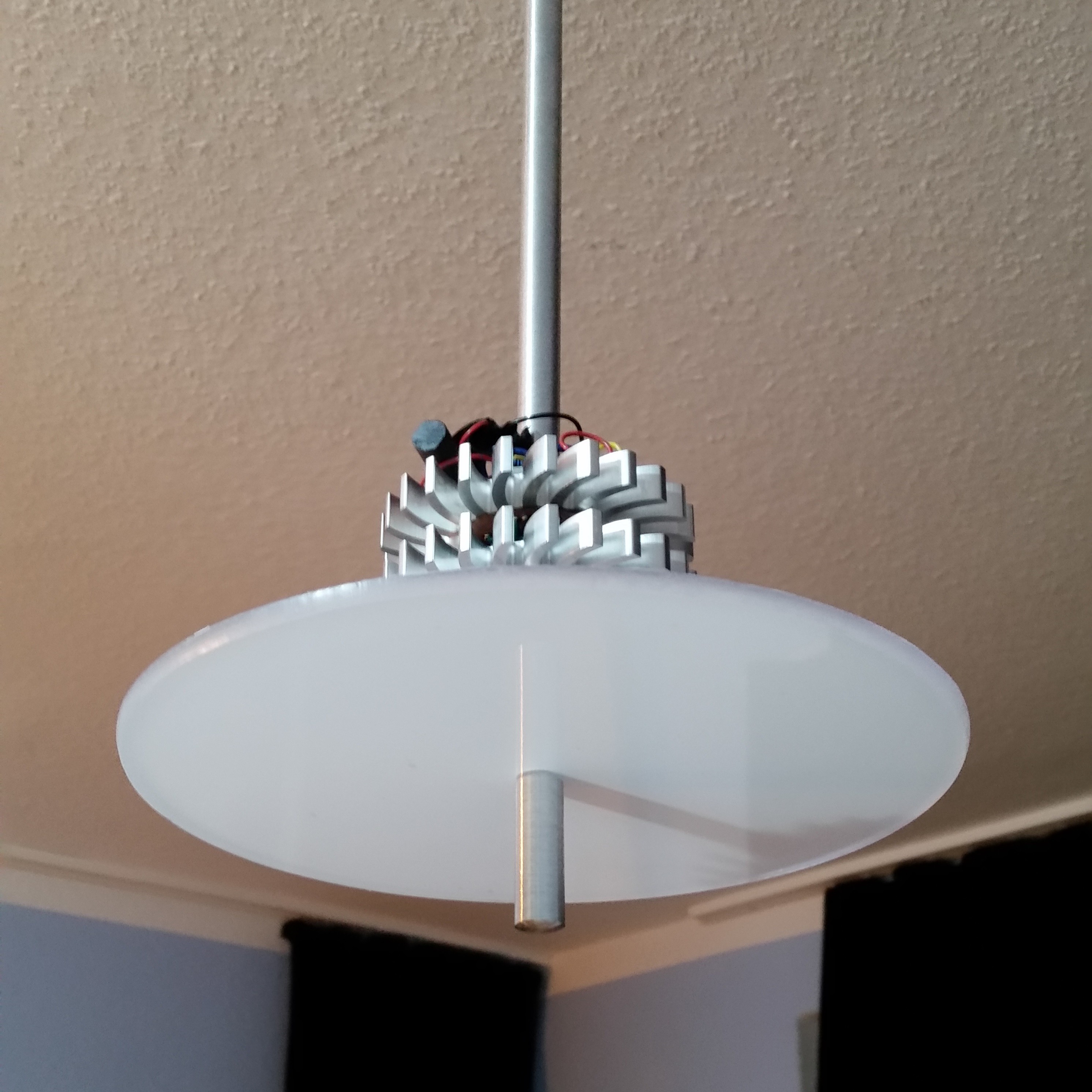
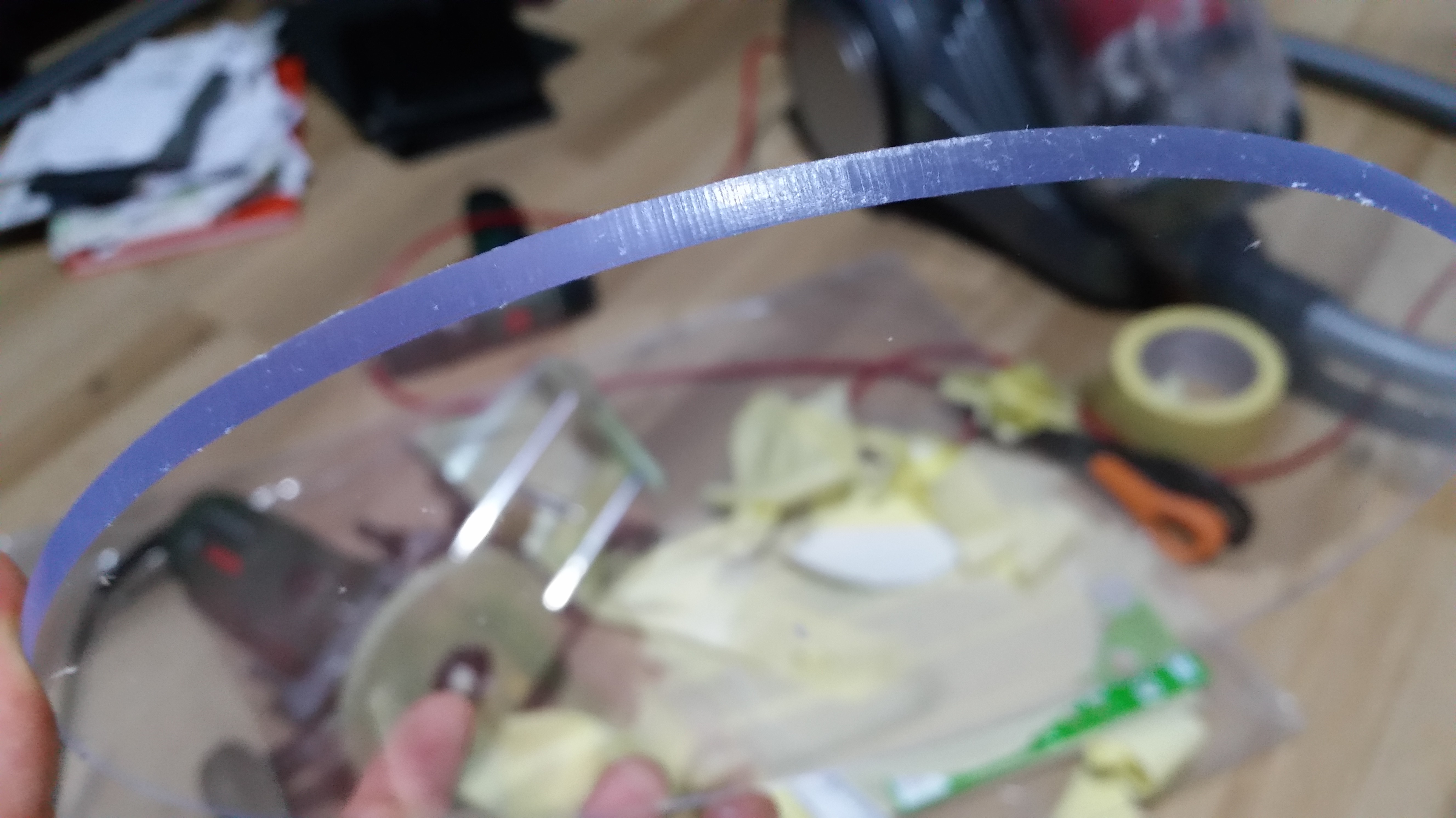
The diffusor plate was milled from 4mm acrylic sheet using a router and lots of protective masking tape. I cleaned up the edge with a 9mm radius head dropped to about the middle, resulting in a nicely rounded edge and a slightly bigger top side, which hides the upper edge from people looking at the lamp from below. Instead of sanding it to achive a matte finish, I covered the plate with some back projection foil. The foil diffuses the light perfectly in all directions and absorbs just a small fraction of the LEDs' light. If you should plan on making a lamp or something that needs to diffuse LED light, I can only recommend this technique. You don't have to buy a whole roll. I ordered an A4 sample piece for less than 2 bucks online.

Thermal Management

The LEDs' waste energy is transported through their board's .5mm FR4, M3 brass screws between the white LEDs and a 12mm to M6 aluminium rod in the center for the orange LED array. The lower heatsink is thermally coupled with the upper one using 3 threaded 10mm x 10mm aluminium spacers. I started with making a perfectly centered M6 thread, so I could screw the board to the heatsink and drill all the tiny holes.

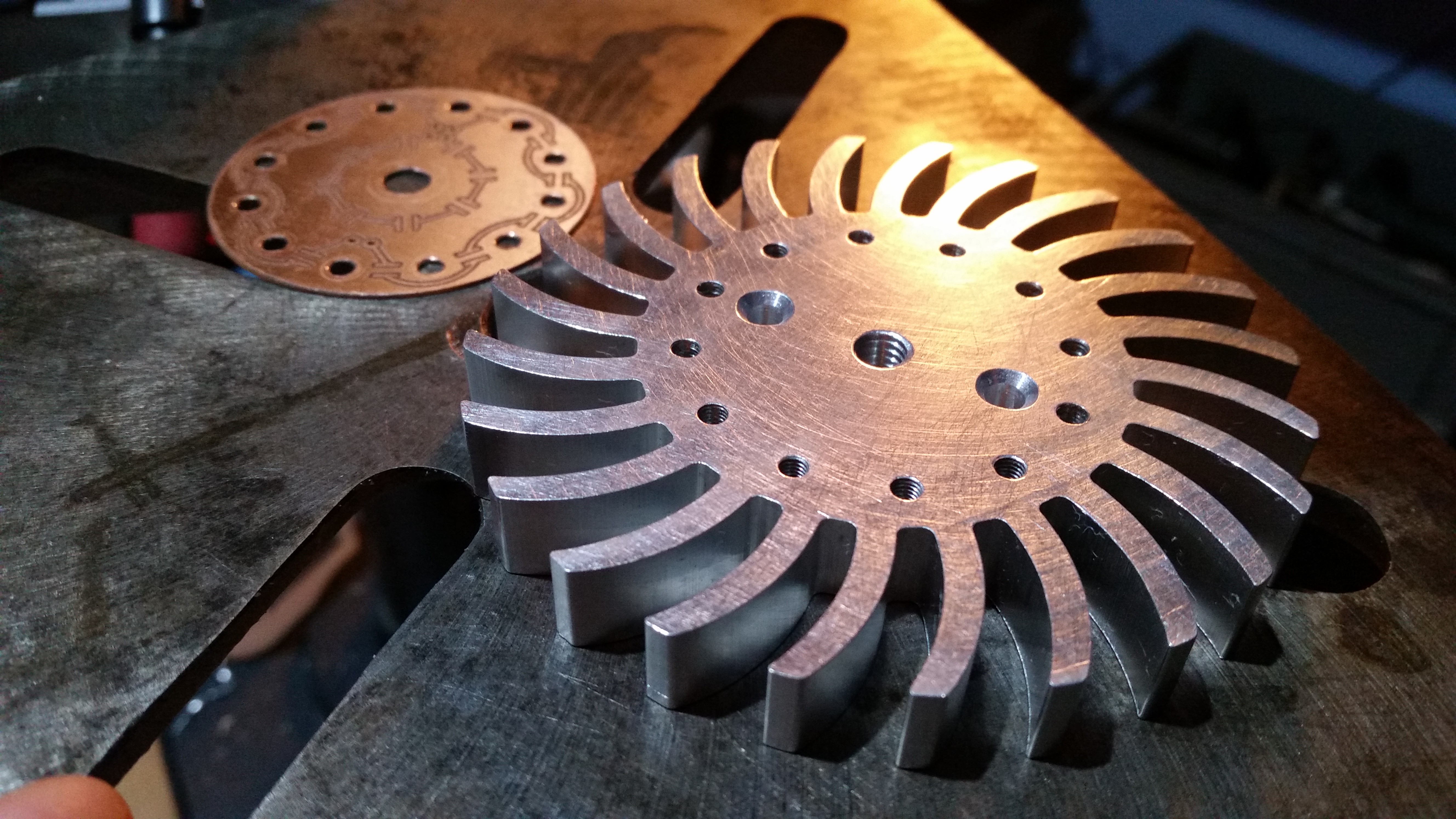
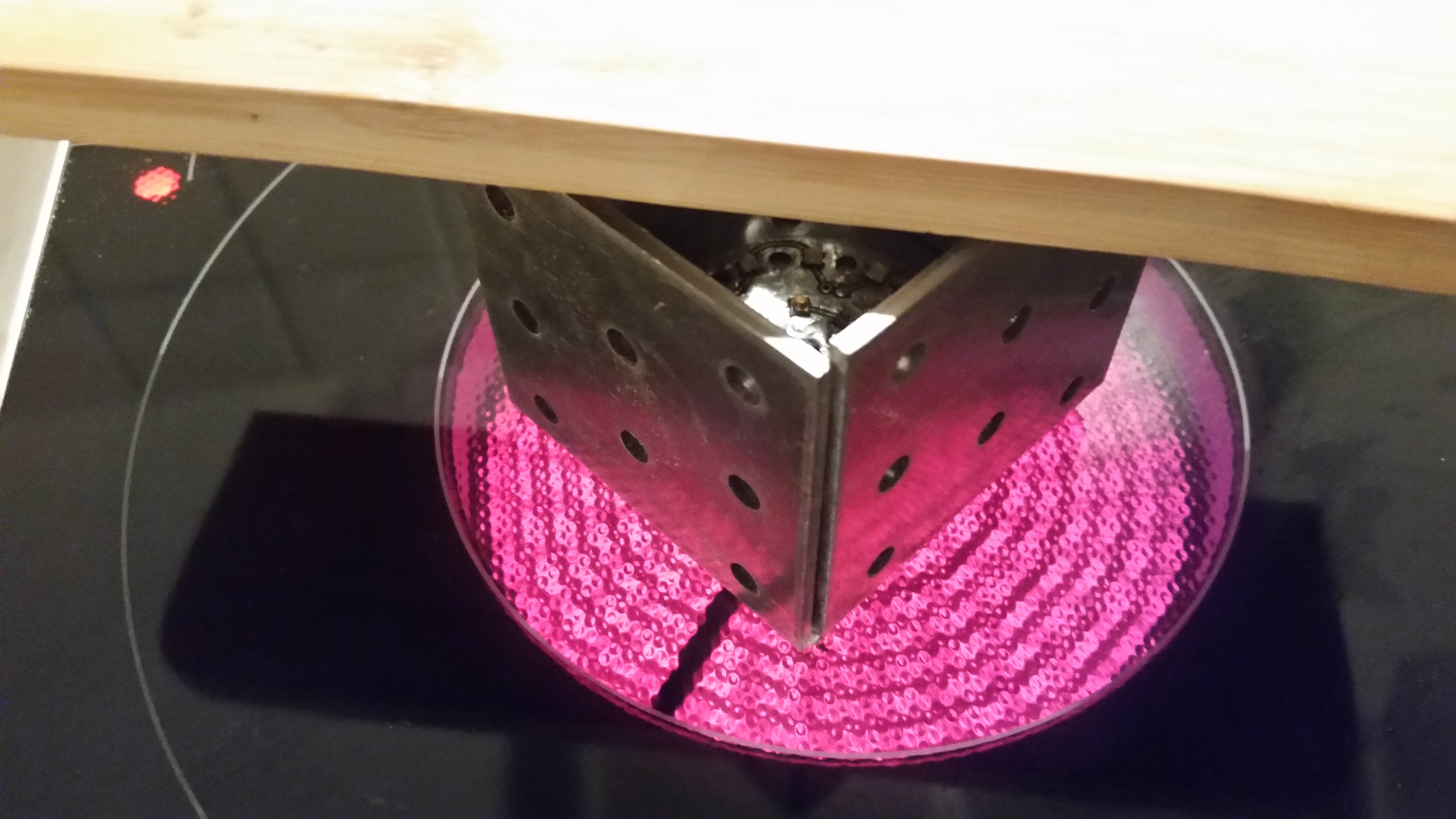
Because the LEDs can not be soldered by hand, I did this step on my oven. The metal brackets keep the heat inside. Then I assembeled everything and applied 1g of thermal grizzly 12.5W/(m*K) paste to ensure a good thermal conductance - especially between the upper side of the board and the screws/rod.


Electronics

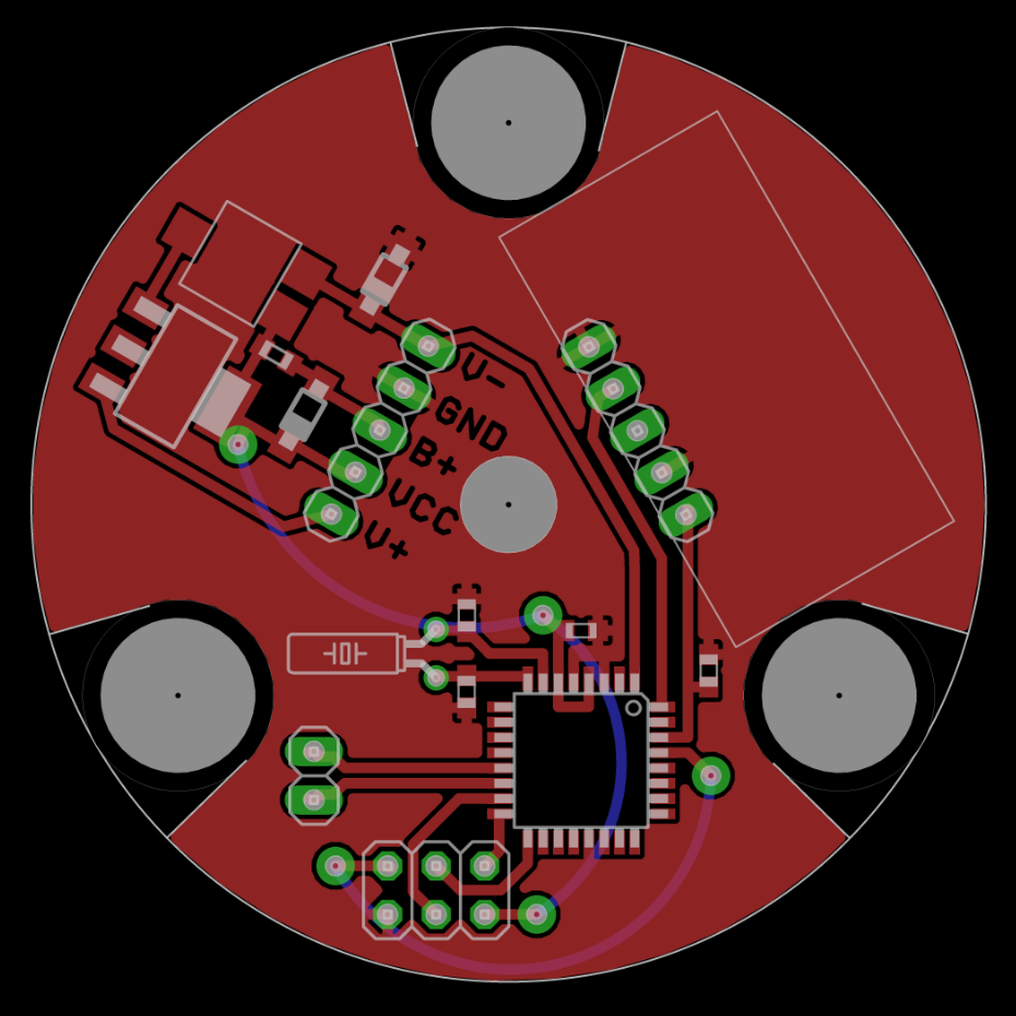
The board sits right between the two heatsinks and is held in place between the three aluminium spacers. It's mostly just an ATMega, a voltage regulator and a DCF77 receiver. I initially planned to have the NiMh RTC backup battery on the board, but then I decided to put it behind the ceiling plate with the power supply so it stays cool and because the heatsinks look better when they are only 10mm apart. How did I route and arrange the parts in a 60° angle? I just turned the whole board. The layout has only a top layer. The bottom layer represents wire connections.

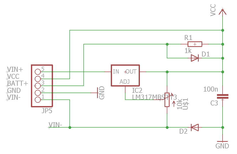
The regulator provides 3.9V and connects to the backup battery via a 1kOhm resistor for trickle charging. The AVR can detect if it is powered by mains or battery. I had to generate a low level when the power supply is switched on, because the AVR needs a low level for its interrupt. This is why the diode is connecting VIN- to ground and not the output of the LM to VCC, like it would be standard procedure. As soon as the light switch is turned off, the voltage between VIN- and VCC drops, resulting in a high level.

Three LM350 provide...

Read more »

asm - 14.07 kB - 01/05/2017 at 13:39

Download

brd - 82.25 kB - 01/04/2017 at 12:52

Download

sch - 521.58 kB - 01/04/2017 at 12:52

Download

sch - 251.22 kB - 01/04/2017 at 12:52

Download

  • 1 × ATMega8L Microprocessors, Microcontrollers, DSPs / ARM, RISC-Based Microcontrollers
  • 12 × Osram Oslon SSL neutral white
  • 2 × Osram Oslon SSL yellow
  • 2 × Osram Oslon SSL amber
  • 2 × Osram Oslon SSL red

View all 30 components

  • Reducing code size

    Matthias Kampa01/05/2017 at 13:38 0 comments

    Using assembler can reduce code size a lot already. These are the techniques I used to implement a RTC including date, DST, leap days, DCF decoding and synchronization in less than 420 bytes.

    Binary is your friend

    How do you calculate if a year is dividable by 4? In C probably using " Year % 4 ". In assembler, this would have been a lot of lines to code. Try to use shifting and other binary operations for calculations.

    Know the SREG

    Another technique you can see in the snippet above is that a comparison doesn't have to be followed by the conditional jump it is executed for. A jump doesn't change the SREG. By jumping to the conditional jump and not coding it twice I could save another line.

    Here is a more elaborate example of SREG trickery. This snippet switches the LEDs PWM and timer off if it isn't between 10 and 11 p.m. and if override isn't activated. Override forces the light to go to day mode. BRLO (branch if lower) is the same as BRCS (branch if carry set), so I just set the carry bit and jump behind the comparison, where the PWM and timer is deactivated. The jump to tLedDay is then performed because the carry is still set. If the comparison comparison against 22 is performed because override is not set, the comparison result will still be persistent after deactivating the PWM and timer and is used for the brlo.

    Use tables and ijumps

    The snippet below reads the length of a month from a table and uses it to wrap the day properly. I saw C code grouping equally long month in comparisons instead, ending up with way more lines of compiled code. Pay attention to the wrapping of the table. In this case, I aligned it with the address 0x0200.

    I did not use any ijumps in this code, but they should be mentioned here too. I would have used an ijump if multiple month would have needed their own function like February does.

    Let your µC's hardware do the work

    Microcontrollers have a lot of built in functions and using it (right) can save you lots of lines. Because the PWMs frequency is not very critical, I just set it to 3600 (the amount of seconds in an hour) so the device has a great resolution with little computational (and coding) effort.

    Don't move data around

    The easiest way to reduce code size is to leave data in working registers to reduce push, pop, lds and sts instructions. Just by not using the SREG in my main loop I saved another 16 to 32 bytes because I didn't have to save its content in every interrupt routine.

    Think out of the box

    Well, there's no recipe for this. Just be brave and don't follow the handbook all the time. Maybe my code can give you some inspiration. Check out how the DCF interrupt doesn't distinguish between high or low levels, why I use the RTC timer with a smaller divider and how the DCFs CRC is calculated on the way.

    Be lazy

    Makros can save time and make code look clean, but if you want to save code space, don't use them. Your laziness will motivate you to code smarter and more efficient.

View project log

Enjoy this project?

Share

Discussions

Similar Projects

Does this project spark your interest?

Become a member to follow this project and never miss any updates