ICE. Integrated Circuit Expanders.
For saving time of all electronics students, makers, hobbyists.
An ease for anyone who just wants to learn electronics, without drowning in
ugly datahsheets, and messy cable connections.
Less time for searching, cabling, error detection.
More time for creativity, proper thinking, developing.
I. C. E.
What it does?
An I.C.E., mainly carries out these actions:
1. Converts package to DIP for prototyping.
2. Arrange relative IO's and power planes for cabling.
3. Clearly indicates the pin connections for testing.
Convertion.
You can solder your package at the bottom of the expander, and add some headers to the both sides.
So your new IC is suitable for almost every breadboard.
If it's already DIP, it needs a bit longer headers for the greater height.
DIP version boards just need this step like the others,
for achieving the advantages of the next steps.
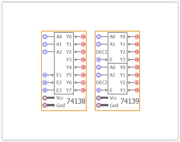
Arrangement.
By these expanders, every package will have a new pinout.
This new pinout is taken into account from a few aspects.
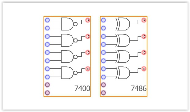
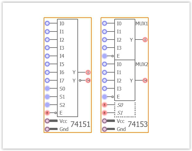
All the inputs are placed on the left side.
All the outputs are on the right side.
Voltage and ground connections are on the bottom-left.
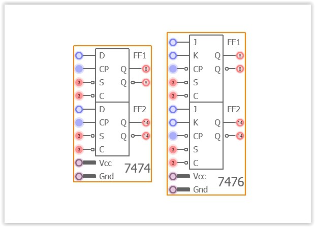
Extra pins like, Chip Select, Enable, Disable, Clock, Shift, Set, Clear, are placed on another functional area.
And any pin that is not an input itself, but related to an input, is located on the left. Same rule is valid for output-related pins.
Different function blocks are placed side to side.
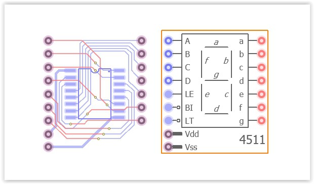
Instructions and tooltips.
For the package is soldered on the bottom, there will be a significant
area at the top for silkscreen, which can be used for symbol based tooltips.
The IC is represented by a general logical symbol as possible as.
Inverted IO and pins are represented by a small empty circle at the end of the pin.
Package related extra features are represented by a dotted rectangular area,
like Common Clock, All Enable, or Chip Reset.
Voltage and ground pins of the entire package, are on the same area for every expander, bottom-left.
If more voltage or ground is available, they are also placed the most reasonable position.
Especially operational amplifier based ICs will need this feature.
In general, almost every coordinate of the silkscreen, will represent a summarized information.
For example, Sinking or Sourcing Outputs, Schmitt Trigger Inputs, Analog Pins will be marked.
FOR MORE DETAILED INFORMATION, YOU CAN VISIT THE PROJECT'S MAIN PAGE:
 Brainy.Baboon
 Mastro Gippo
 Les Hall
 sjm4306