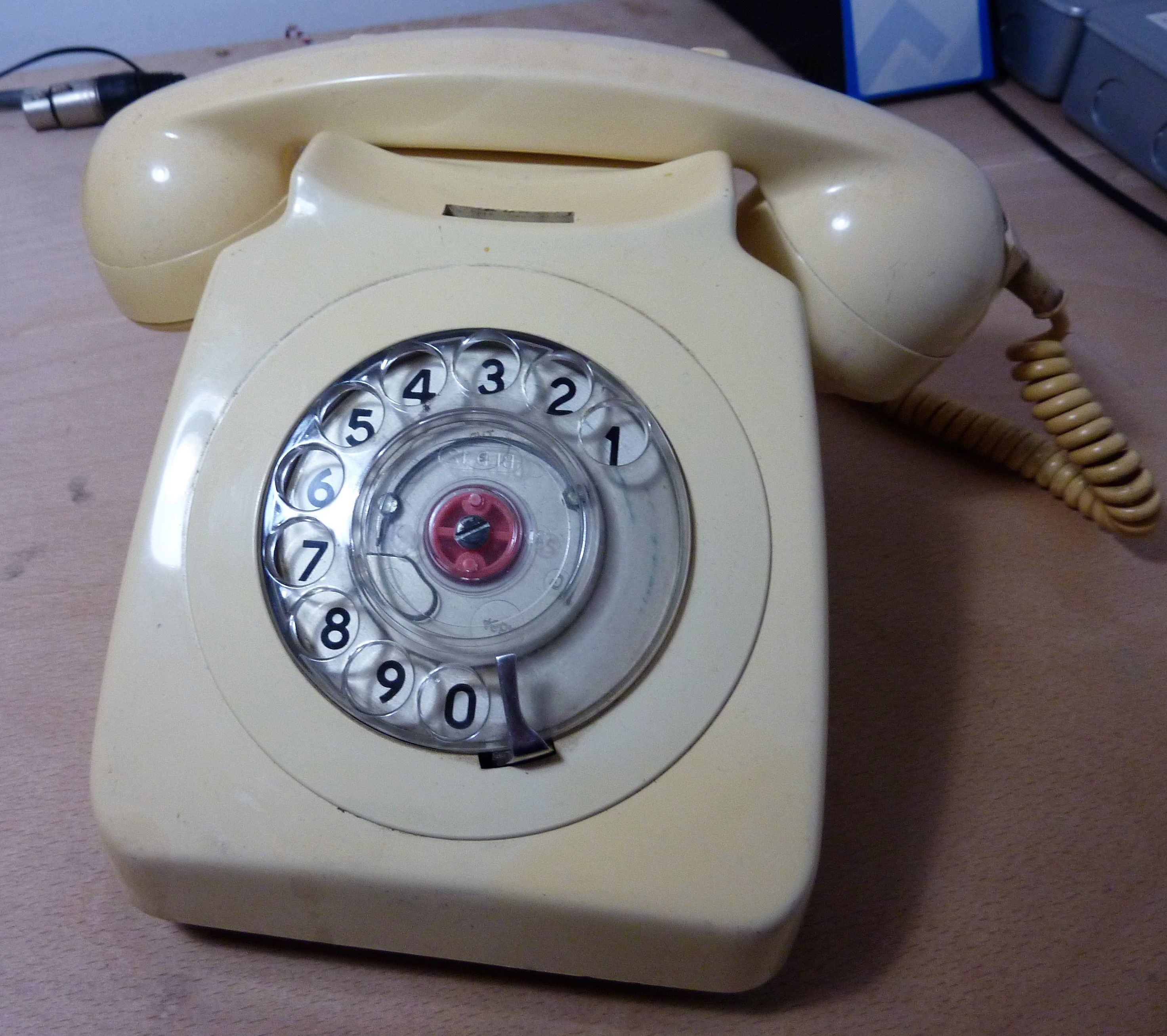
The phone in question was a GPO 8746 in a rather fetching shade of cream apparently officially called "ivory", a product introduced in 1967. Wiki page on old GPO standards linked for anyone seriously interested. I should say, it was chosen entirely because it was the first one that was found in the first second hand shop walked in to, but it did do a great job. Certainly looks the part, if nothing else. Rotary dial still works, by the way. Although it wasn't used at all in this, would love to find some other use for it at some point in the future - would seem a shame not to.
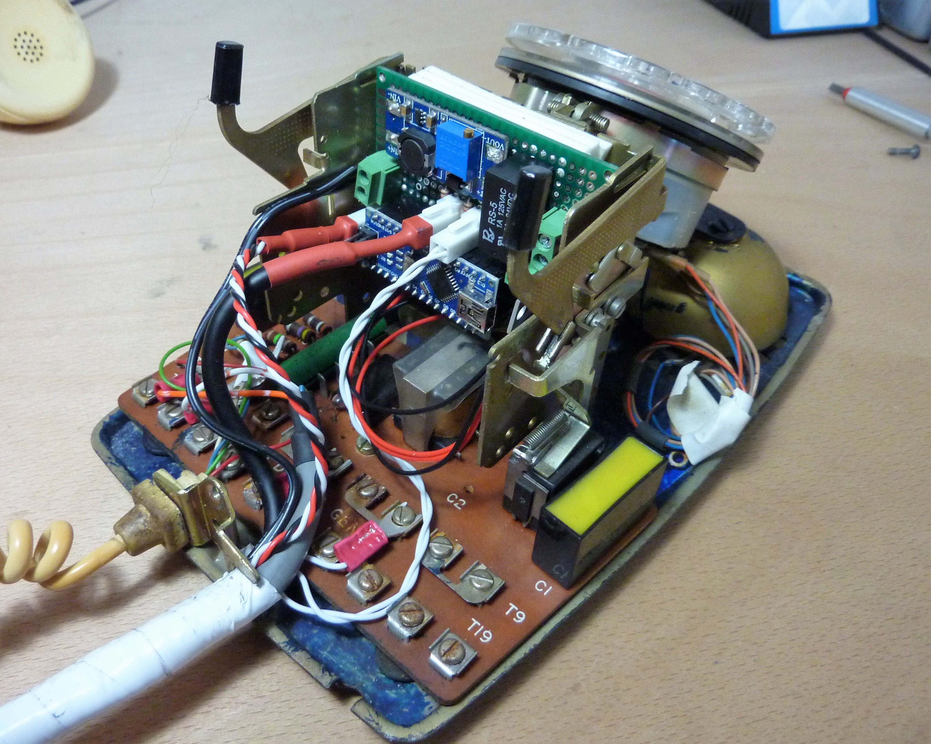
Oh, and a little bonus shot (from behind) of the finished article with its casing off.
The first order of business was to take control of those oh-so-important bells. I ruled out early on trying to control them through some sort of emulation of phone line modulation due to it seeming like a massive pain after only a little bit of research, so I would need to strip it back a bit. The ringer is controlled by two electromagnets which fortunately state some of their own specifications on the side. Specifically that they are 500Ω, and a bit of research lead me to believe that they get a control signal in the neighbourhood of 50-60V. This, however, is with the two run in series, so if they were instead arranged in parallel, perhaps they would work from only 24V? Turn out, they will. This was convenient as I happened to already have a 24V max output boost converter based on the LM2577.
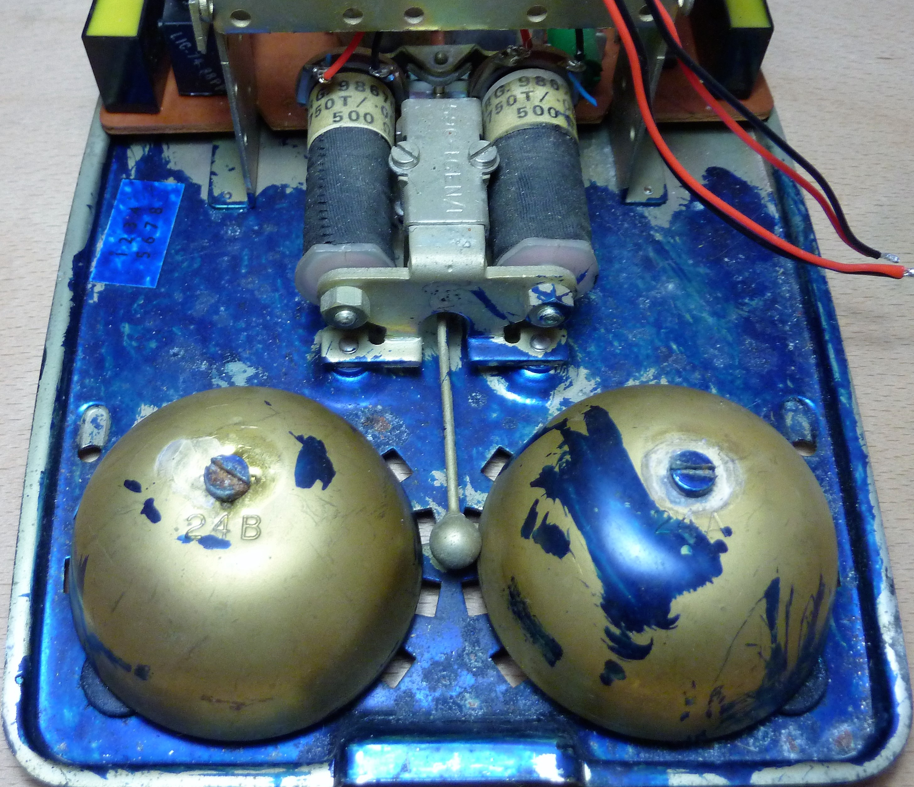
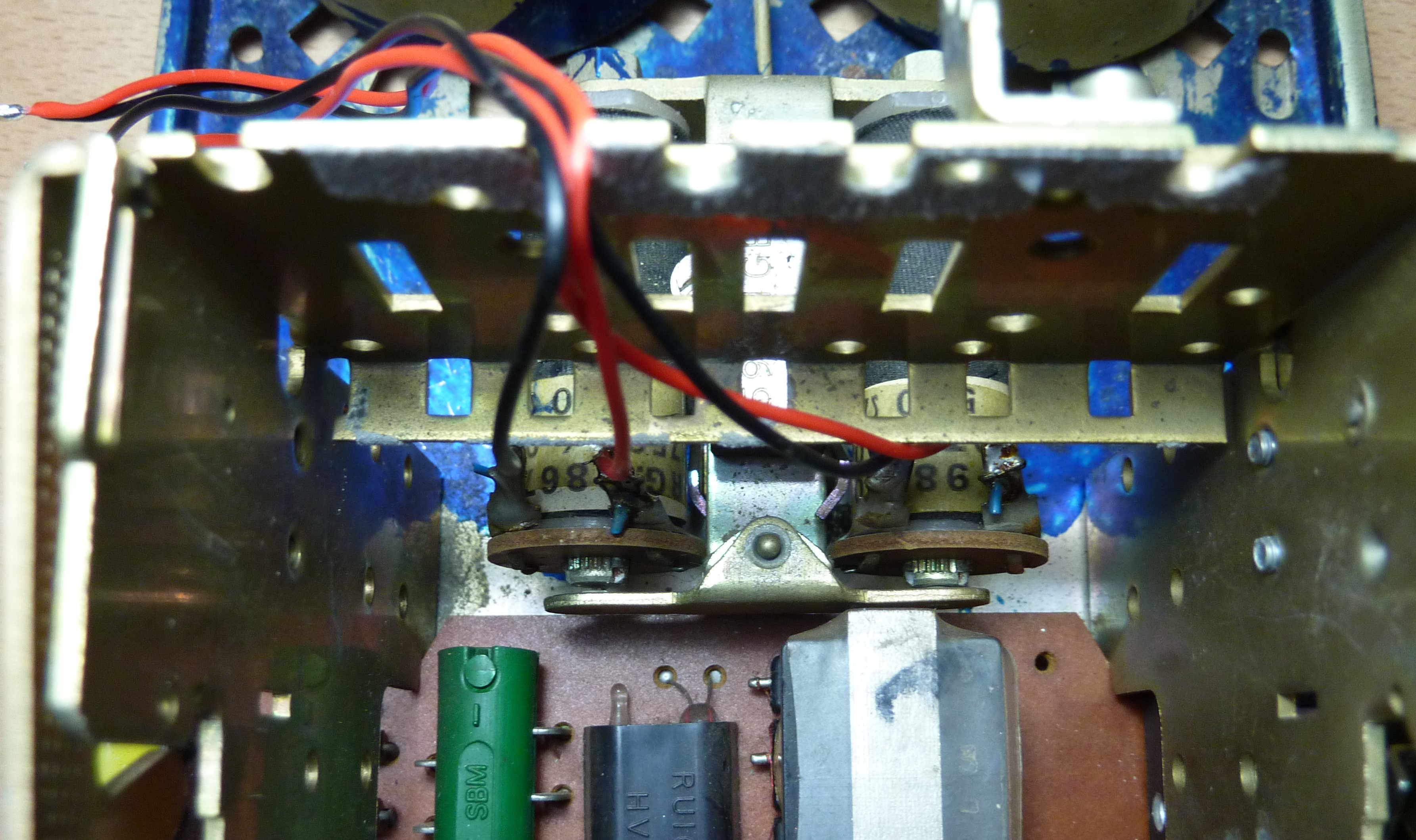
Electromagnets are grey-wrapped cylinders at top of image above. The long shaft with the striker on the end pivots just behind the electromagnets (see image below) and strikes each bell in turn. If you look closely you can see that the bells are labelled 24A (on the right) and 24B (on the left). Not sure what the numbers mean specifically, but it does show that the two bells are different, which is what grants the phone that distinctive drrriiinnnggg. (Even less sure why the thing is half full of blue paint, but let's not worry about that).
Initially, I had planned to switch each coil individually from 0-24V and control the ring, but experimentation showed that not only does the appropriate coil have to be energised, bu the opposite has to be energised the other way. A full bridge would be the sensible, modern, solid-state way of going about that, but I didn't have one to hand. I did, however, have a few relays sitting about. Specifically, a DPDT (double pole double throw) relay of the appropriate current and voltage ratings (30V and 200mA as a reasonable minimum). The circuit used can be seen below. The signal described as D_CONTROL was, in this case a 0-5V signal from an Arduino, but it could be anything really. A high will force the striker against one bell and a low will force it against the other. Alternating this signal results in the desired ring.
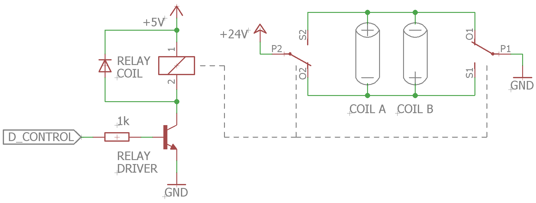
A double pole relay should be used over two single pole relays, as the two switches will be mechanically connected, ensuring both switches will never both be in the position. Otherwise, one would be at risk of 'shoot-through', a situation where one effectively shorts the supply through your switching devices. It is a situation to be avoided.
The use of an Arduino for control made it very easy to get the timings just so. The standard ring timings (in the UK) are:
RING for 0.4s
OFF for 04s
RING for 0.4s
OFF for 1.4s
and repeat as required. With the bells striking signal (i.e. D_CONTROL) during the RING period having a frequency of 20Hz.
Now that the phone could ring on command, the next order of business was the control interface. Initially, the plan was to control it entirely over MIDI. MIDI was chosen as a protocol as it is very easy to work with on both Arduino and the software that would be used to playback the A/V cues (in this case, Resolume Arena). In the end however, the initial trigger for the phone to ring was performed not over MIDI but just with a button on the end of a long cable, with only A/V cues being passed over MIDI. As for the MIDI, I just used the standard, boring MIDI library that comes bundled with Arduino, which has some excellent tutorials for first timers and the forgetful. Particularly easy as now it would exclusively act as a MIDI broadcaster (i.e. no need to receive messages). I would also need to hijack the sensor that detects the handset somehow.
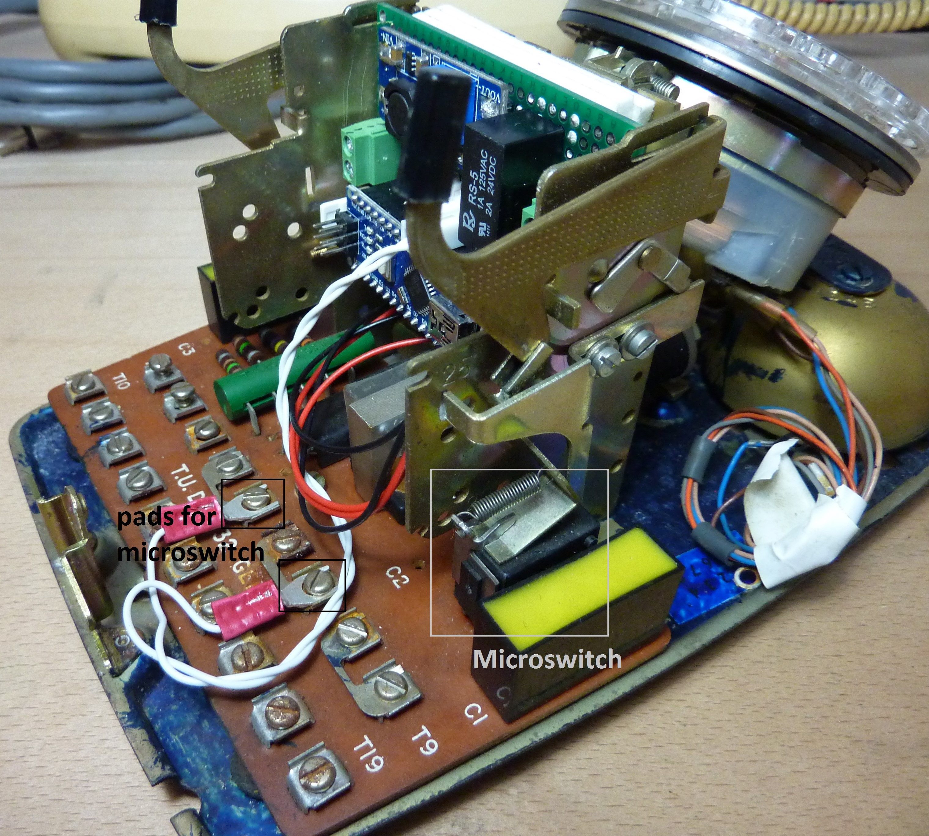
Tracking down the means of detecting the handset was first on the list, and was not a great challenge. The two plastic tipped arms clearly seen at the top of the image below protrude from the case and are pushed down when the handset is down, closing the circuit in the microswitch labelled. This switch was electrically accessible through the pads labelled in the image below (found through trial and error).
This microswitch and the aforementioned remote switch to trigger the device ringing initially needed to be interface with the controller. To avoid the need for de-bouncing and due to the simplistic nature of the application, these inputs were polled rather than triggering an interrupt. For those not familiar with the concept or switch de-bouncing, I link in an great article on the subject written by a friend from my local hackspace. A 10k pull-up resistor was used on both pins resulting in a logical low when the switches are depressed.
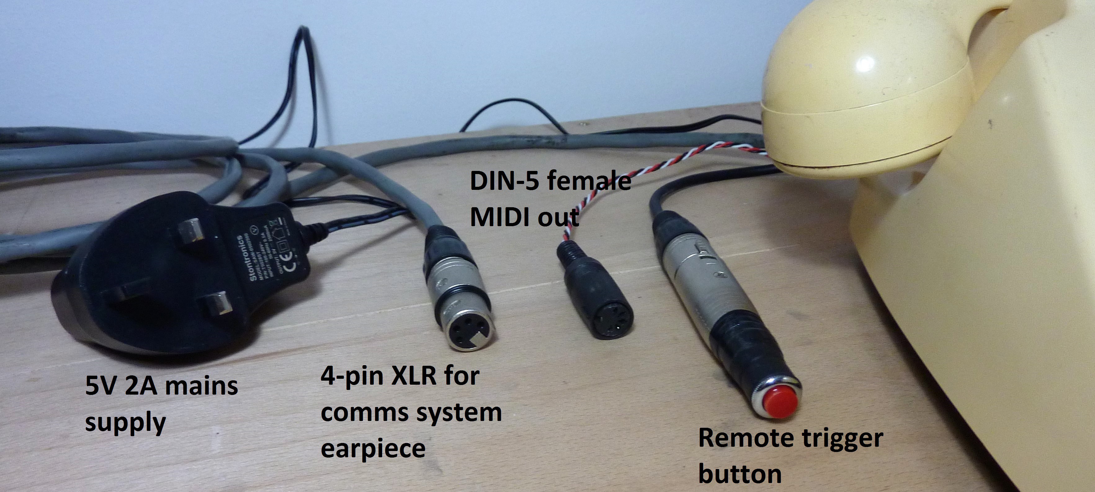
For ease of line extension, and by virtue of my having the parts lying around, the remote trigger button was mounted inside a 3-pin XLR connector, as seen on the right of the picture below. The MIDI output was handled on 5-pin DIN, as is standard. There was also a 4-pin XLR for earpiece and a mains power supply. The system overall draws in excess of 5W, so a standard 5V 1A supply will not do.
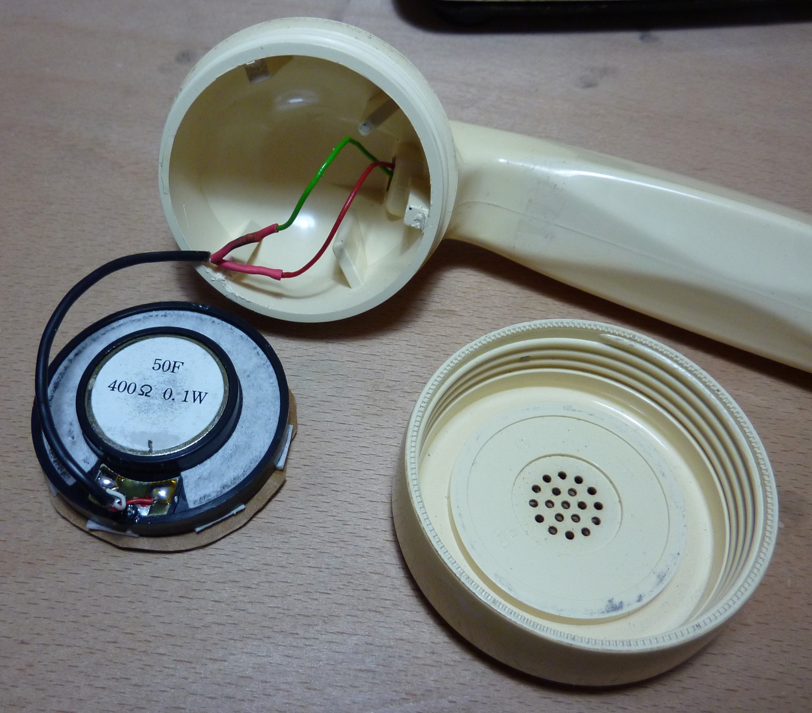
I didn't sort the earpiece personally, but a suitably elegant solution was arranged. The loudspeaker from a standard wired comms headset (specifically a Canford Audio SMH210) was salvaged from a broken unit, enabling interface with an extremely flexible, standardised system. The cables that ran to the original earpiece were re-purposed in order to maintain the aesthetics. 4-pin XLR is the standard interconnect for this type of system, usually two pins for headphones and two for microphone, though obviously only half utilised in this instance.
There was little opportunity to film it in its final setting (A/V cues and all) but it worked just as had been hoped. However, below is a extremely potato video I took on my phone to address a claim of "pics or didn't happen". Thought I'd share, embarrassing in its quality (or lack thereof) though it is. All in all, it worked. I've included in the little Arduino script that ran it in project resources for anyone who is seriously interested. Suffice it to say, there's not much to it.