Video demonstration
1kB?!
So why even program a tiny sound generator in assembly?
The inspiration for this was the 1kB contest. Also I wanted to see if I could really do it. This resulted in a lot of thinking about minimal implementations of algorithms and also in my first assembler project. It turned out to be a lot of fun, too!
So how do I know that it is smaller than 1kB?
First of all, otherwise it wouldn't even fit onto the chip. Secondly AVR Studio (which was used to assemble this project) told me, that only about 760 Bytes are taken.
Still don't trust me?
After disassembling the hex file again with
avr-objdump -m avr -D blues_generator.hex the last instruction was on the address 0x2F6 which is 758 in decimal. It was a 'ret' instruction which is 2 bytes long, so the program is only 760 bytes big and consumed less than 75% of the chip.Other than the main flash no other memory (e.g. EEPROM) was used.
Musical Theory
As already mentioned in the short description, this circuit will produce a 12 Bar blues . The original 12 Bar blues consists of the tonic (T; the first note in the scale of the key), the subdominant (S; the fourth note) and the dominant (D; the fifth note).
12 Bar blues
These three are played as chords according to the following sequence:
T T T T
S S T T
D D T T
I wanted a little bit more retro sound in my blues generator so used arpeggio for the chords which in my case just means quickly switching between the tonic and dominant of the current note. This was also widely used in 8-bit tunes to overcome the voice limit of sound chips (you will probably not what I mean when you hear it).
Walking Bass
These chords are accompanied with a walking bass in the key of the currently played chord. The walking bass uses the first, third, fifth, sixth and seventh note of the scale of the current chord like showed in the following scheme:
1 3 5 6 7 6 5 3
Improvisation
The last part I utilized was a very simple improvisation on top of the chords and the walking bass. Improvisation in jazz and blues is mostly done by using the pentatonic scale (consisting of the first, fourth, sixth, eighth an eleventh note of the key) . This scale is independent of the current chord but it stills is in harmony with all chords.
In this implementation the AVR decides to go up or down one note with a chance of 37.5% each. It repeats the same note with a chance of 12.5% and doesn't play anything if none of the above is chosen. Although being very simple, this algorithm creates satisfy able results.
The Circuit
Aside from the AVR, power connection and reset button the circuit is dividable into three parts: the LED's, the temperature sensor and the sound output.
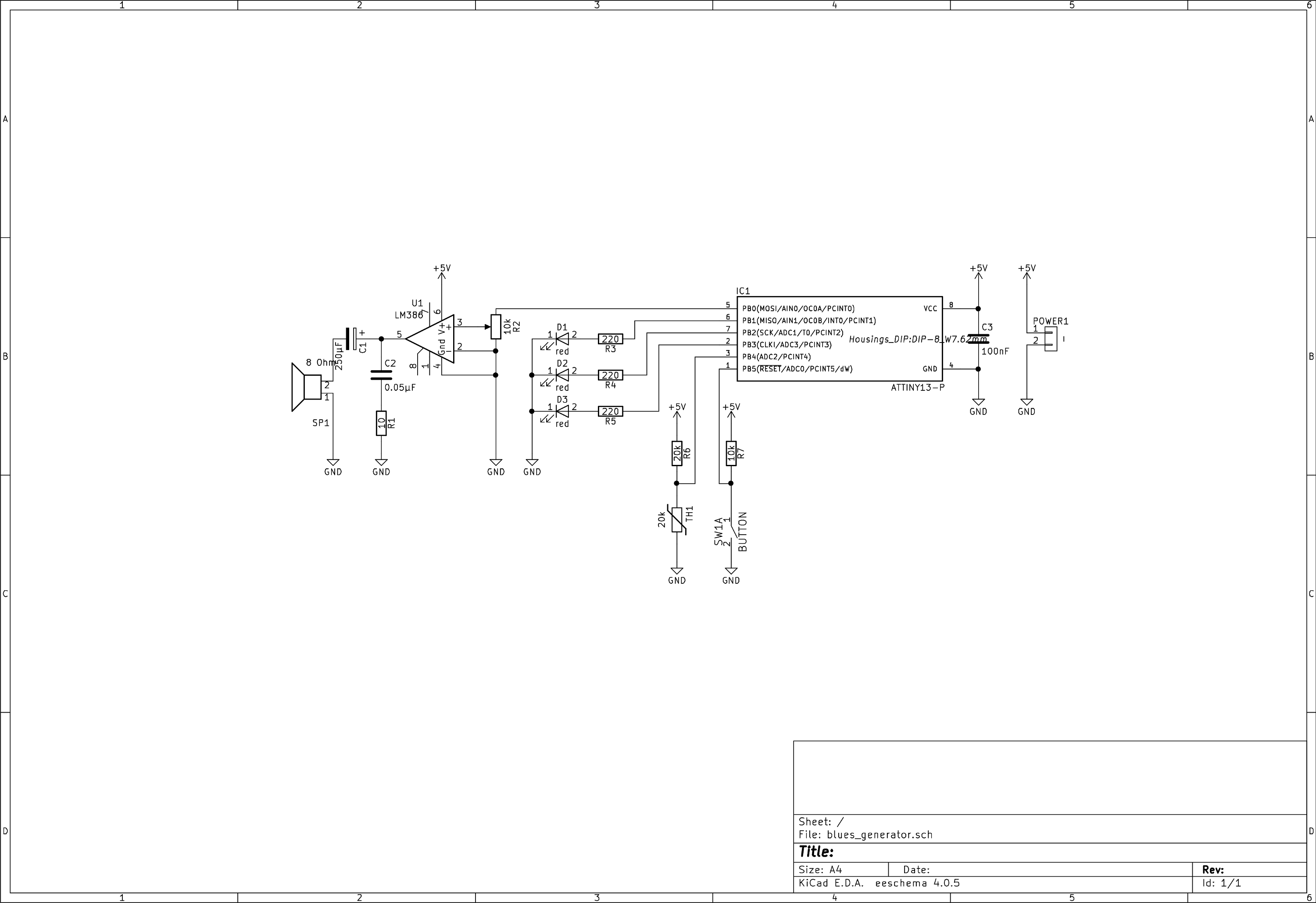
LED's
The LED's are simply used to output the current position of the walking bass (in binary of course). These were added very late to the project because it was easy to implement, the resource were there and it looks way cooler if something is blinking.
The LED D1 shows the most significant bit.
Temperature sensor
The temperature sensor is a simple voltage divider and is only used to initialize the random number generator with a 'random' number (read through the ADC).
Sound output
The sound output surely looks like the most complex part of the circuit although only consisting of an audio amplifier chip in it's minimal configuration. The potentiometer can (theoretically) used to control the output volume but as the minimal amplification of the audio chip is 20, most position will amplify the signal to the maximum.
The Software
The software is by far the most complex part of the project.
The following parts should provide an overview. For more technical details please take a look at the annotations in the source code.
Initialization
After the assigning register names and the interrupt table begins the general initialization (SREG, stack pointer, etc.) followed by the ADC initialization. This is kept very simple and it's only purpose is (as mentioned above) to read out the value of the temperature sensor and use this as the initial value of the random number generator.
After this is done the AVR loads all necessary musical data into the RAM beginning with nearly two full octave starting at the (fourth octave) C. This allows picking any note as the key and just moving the memory to align the randomly selected key at the first memory address. The random selection requires a value between 0 and 11. This is generated by generating 3 random numbers (the first is smaller than 2, the second smaller than 4 and the last is smaller than 8). Adding these together should create the wanted value. After only notes of the wanted octave are selected the walking bass sequence is loaded at the memory after the octave directly followed by the chord sequence and and last the pentatonic scale. This allows for easy sequential reads (at least most of the time).
Now that everything is loaded into the RAM the initialization of the timer and registers can take place. The timer is (obviously) set to fast PWM mode with a prescaler of 256. At the full 9.6 MHz (disabling the x8 divider fuse) of the internal oscillator this result in 37.5 KHz which is quick enough to output most of the human hear able sounds. The interrupt on compare match is also enabled for time keeping duties as this chip doesn't has any other reliable source. The timer also increments a global counter every 256th execution which results in about 146 Hz.
Main function
The first priority of the main function, after setting start positions for several counters, is to handle the arpeggio effect therefore switching between tonic and dominant every fourth global counter increment, which is about 36 times per second. Every 64th step (~2.3 seconds) the walking bass switches to the next note. Once the walking bass is done with it's sequence, the next chord is played.
The improvisation takes place at the same speed of the walking bass. If the upper or lower limit of the current octave is reached, the value of the selected note is divided (or multiplied) by two moving the note on octave up (or down). This is only possible due to the fact that the frequency of a note in the octave above the current is exactly the double of the current frequency (e.g. A 4 = 440 Hz --> A 5 = 880 Hz & A3 = 220 Hz). The upper limit for this is set to 3 octaves above / below the key because the 8-bit precision prevents clean notes after above this.
At the end of the routine a new random number for the next improvisation is chosen.
Timer
Inside of the timer interrupt function the waves are rendered. For the sake of simplicity only square waves are used. This implementation provides three independent voices allowing three simultaneous notes in different volumes to be played.
The wavelength information is the number of cycles of the timer function until a half period is reached. This makes the rendering process very convenient and the numbers fit well into 8-bit registers.
Random number generator
A linear congruential generator was chosen because of it's simplicity. The parameters are chosen to make the implementation as small as possible.
Links for further reading
Musical Theory:
- 12 Bar blues https://en.wikipedia.org/wiki/Twelve-bar_blues
- Walking Bass https://en.wikipedia.org/wiki/Bassline#Walking_bass
- Pentatonic Scales https://en.wikipedia.org/wiki/Pentatonic_scale
- Arpeggio https://en.wikipedia.org/wiki/Arpeggio
- Note Frequencies https://en.wikipedia.org/wiki/Musical_note#Note_frequency_.28hertz.29
Random number generation:
- Linear Congruential Generator https://en.wikipedia.org/wiki/Linear_congruential_generator
Datasheets: