 Param Aggarwal
Ultrasonic distance sensors like the HC-SR04 work by emitting a tiny pulse of ultrasonic sound and then measuring the time taken to return. These are typically used to detect the presence of obstacles around things like a quadcopter, robotic car or robotic arm.
I wanted to experiment with using them for mapping the walls of my room. The way it would work is that I would rotate the sensor and at each point while measuring the ultrasonic sensor reading, I would also read the value from my magnetic compass, hence I would know exactly what direction I am facing in.
With that thought, I collected all the parts and connected them on a breadboard.

Here you see the red LSM303DLMTR Tilt Compensated Compass, as well as the blue Arduino Pro Micro. There are some LEDs that I planned to use, but am not using. I wired all the trigger pins together, while each echo pin goes to a separate pin on the micro.

I have 4 sensors here, which is slightly redundant - but my eventual goal was to point them in 4 different directions to not have to rotate the setup a full 360 degrees. Here, I simply use the reading which is the least among the 4 to avoid spurious readings that are cause by echo's due to slanted walls or previous emissions.

Please see the below code section to find the code. It simply takes readings from the compass and 4 sensors one after the other and prints them to serial. One line for each batch of readings. Also, there is a Processing sketch to visualise all this data sent.

For each heading value in degrees, I drew a line with the length of the distance read by the sensors. This visualisation was expected to be a square - as my room is a small 3x3m square, while the range of these sensors is upto 4m.
Unfortunately, it appears circular instead of a square - which is the shape of my room. You can notice a wall showing up as a flat line on the right side. But other than that the values seem to be all over the place.

Here is another one in which I tried standing at the corner of the room and then rotating while standing in one place. Here, the corner is much better visible. But why isn't this working as expected?
I spoke to my college friend Kirti Dhwaj who was the go-to expert in matters of signal processing. He first asked me what width of beam I was using and if there was any interference pattern of the sensors. The questions confused me, because I expected to simply use the modules as they were built and didn't want to bother with the underlying signals.
But after further discussion with him - he made a very nice point - that the echo's from the walls will make it seem that everything is as close as the nearest wall!

You see, the beam sent from the sensor gets quite wide as the distance increases, so even if the sensor is trying to read the distance to the corner of the wall, it is actually receiving the fastest echo from the wall closest to it!
Hence in our plot above - we don't actually see the corners of the room. This is the reason why it simply appears like a circle. Thanks to Kirti, I finally understood it!
It was an incredible learning experience for me to attempt this practically. Imagining something working and actually seeing it working are two vastly different things.
Future work:
So the way to fix this is to use beam forming using a phase difference between the sensors. See this other Hackster project for more info: Spread Spectrum Phased Array Sonar.
Unfortunately this requires hacking into the internals of the sensor and heavily depends on the use of an oscilloscope which I currently do not have. Maybe you could try it out! Technically with 4 sensors, we should be able to do a phase array sensor in two dimensions instead of the single dimension in the above article.
But hey! Thinking how something might work, is vastly different from seeing it work. Good luck!


 Rex Garland
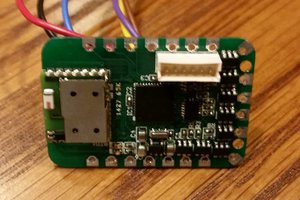
 Statutory Therapy
 Minimum Effective Dose
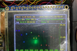
Hi Param,
"... reading all over the places ..."
I had little success getting consistent results from these sensors. My results are similar to yours.
Other issues include:
Depending on the source of your HC-SR04, the timeout can be more than the documented 38ms. My units were around 200ms. This is a problem because these sensor can miss a pulse every now and then. Retrigging the sensor before the timeout returns a zero or near zero reading.
I don't know why but the sensors can suffer "dead spots" or more precisely "dead directions". Probably due to nulls in the interference patterns. In theory a multi-sensor array would bet around this but I had no great improvement.
Another issue (not related to this sensor) is that a wall at more than 15 degrees off perpendicular may not return a response.
Regards AlanX