 nater
naterThis project demonstrates how precision manual PWM can compensate for the non-linearity of a human's perception of light intensity, creating multiple visually appealing light patterns, all within 1kB of program space. The application was a retrofit of an Ikea light fixture for use as a Christmas tree star, and the user controls were fitted into a professional-looking package made with common tools and a shoestring budget.
Non-Linearity of Human Perception
A human's perception of light intensity is non-linear. As an example, the perceived difference between 1% and 2% duty cycle lights is much greater than between 99% and 100%. The result when increasing standard PWM values for lighting is the light will ramp up to almost full intensity very quickly and subsequently only gradually increase in intensity.
To compensate for this, an algorithm is required that increments the intensity value with small steps on the low end and larger steps on the high end--an exponential algorithm. One obvious solution would be iteratively using the following:
Seeing as the target device (ATtiny2313A--I had on hand and am familiar with) doesn't have a multiply instruction and that a goal was to keep the program space usage to 1kB, this obvious solution would not meet the project requirements. Instead, a less program space intensive algorithm was devised and used. Counting through consecutive values while multiplying by two (a left bit-shift) every 16 counts results in an approximation of an exponential function with values like this:
...
0b0000001000000000
0b0000001000100000
0b0000001001000000
0b0000001001100000
...
0b0000001111100000
0b0000010000000000 <-- Bit shift; restart count with leading '1'.
0b0000010001000000
0b0000010010000000
0b0000010011000000
...
0b0000011111000000
0b0000100000000000 <-- Bit shift; restart count with leading '1'.
0b0000100010000000
0b0000100100000000
0b0000100110000000
...
Manual PWM
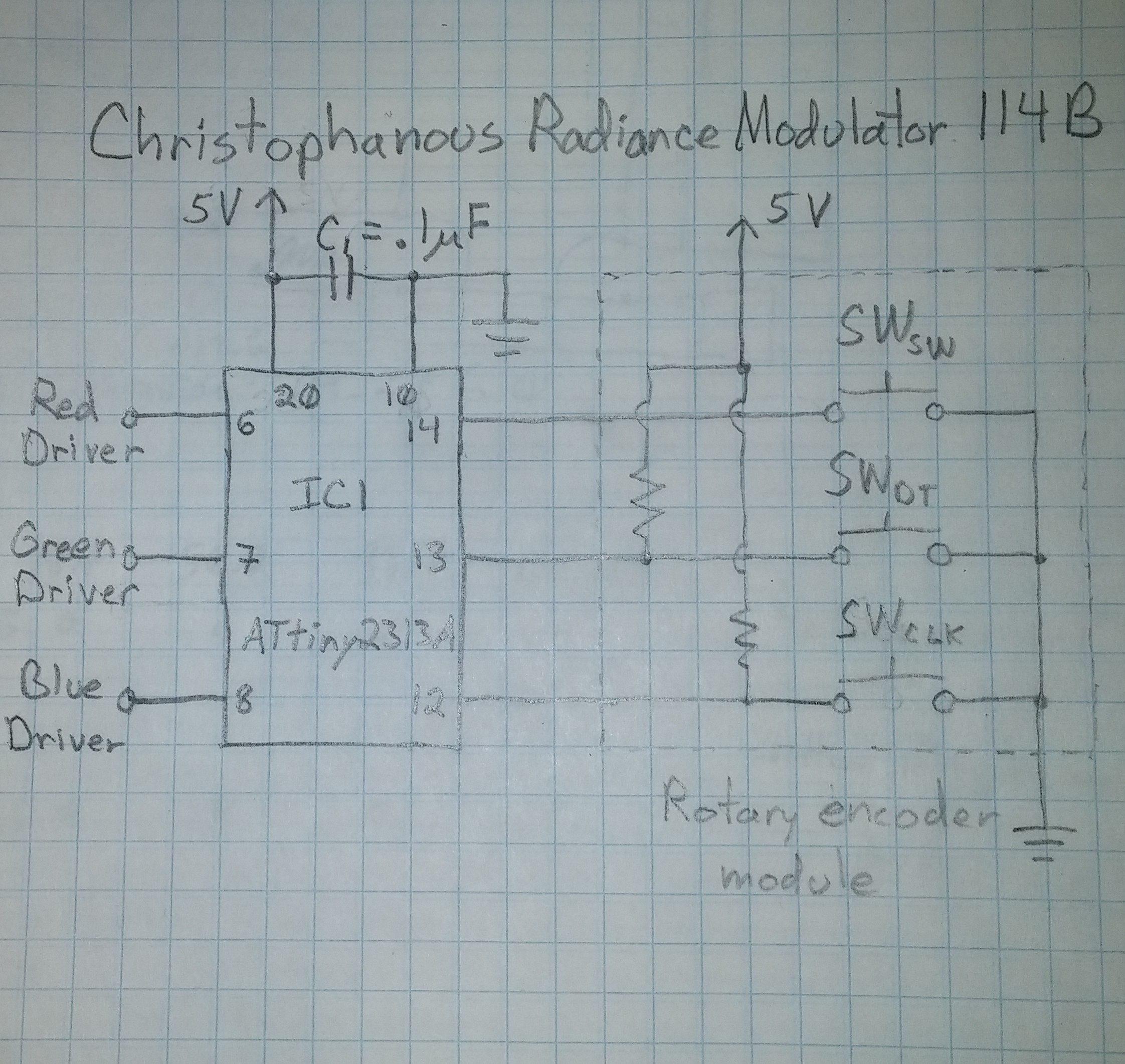
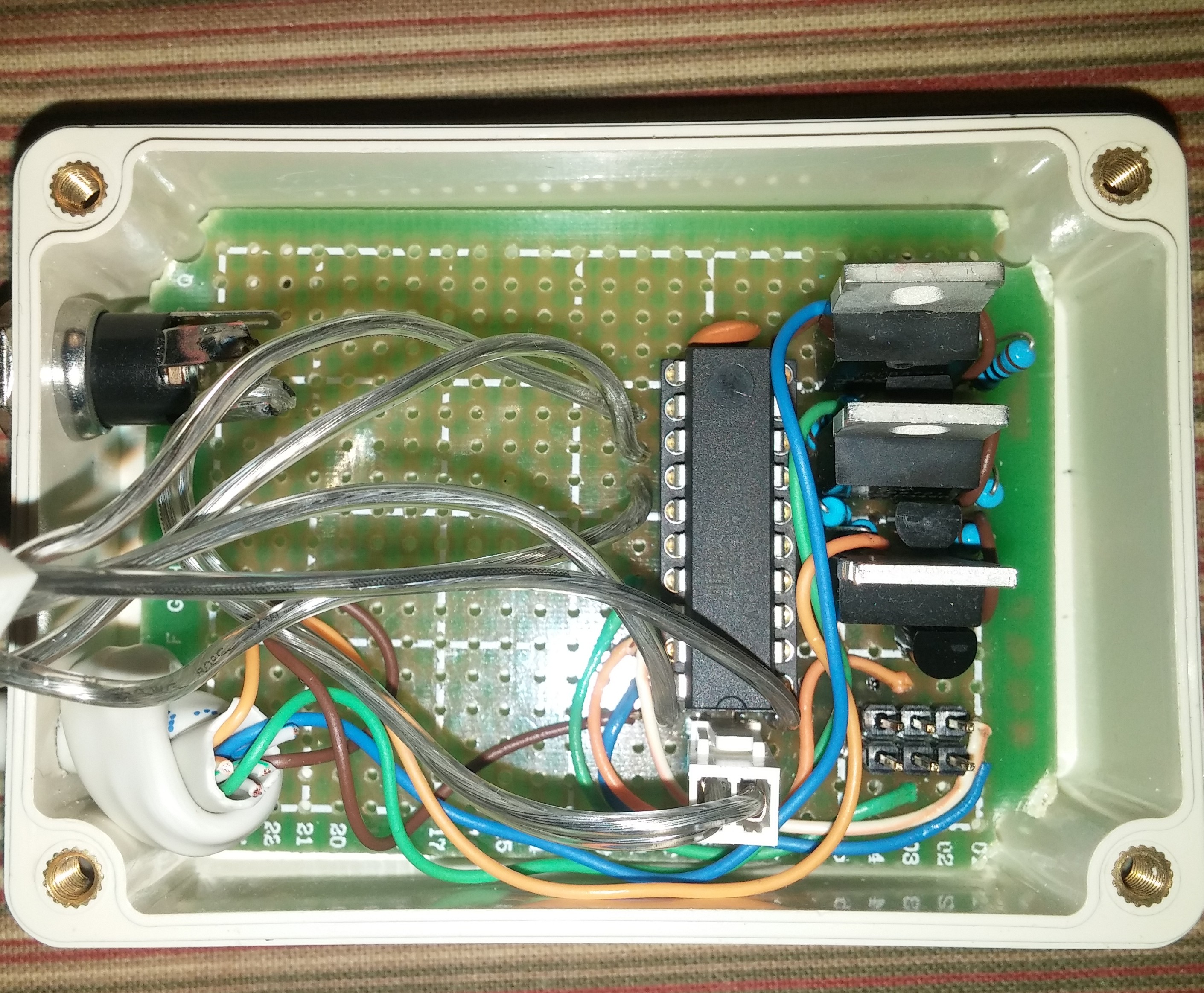
For a larger dynamic range of light intensity and smoother brightening and dimming, 16-bit PWM was chosen. As the ATtiny2313A has only a single 16-bit timer with only two PWM channels, a manual PWM scheme had to be employed to modulate the three color channels simultaneously.
The 16-bit overflow interrupt is used to mark the beginning of major frames--a major frame lasts 2^16 MCU cycles. The major frames are split into four equally-timed minor frames. Tasks are split between these minor frames so as to prevent calculations and color switching from interfering with each other and causing glitches.
Minor frame actions:
- 1st minor frame: Most calculations performed, appropriate colors turned on, and setup for on/off switching of 2nd minor frame.
- 2nd minor frame: Appropriate colors switched, red turned off at precise time, and setup for on/off switching of 3rd minor frame.
- 3rd minor frame: Appropriate colors switched, green turned off at precise time, and setup for on/off switching of 4th minor frame.
- 4th minor frame: Appropriate colors switched and blue turned off at precise time.
The calculations for on and off switching are performed in the overflow interrupt routine for the 1st minor frame. Timer compare A interrupt routine is used to mark the beginning of the 2nd-4th minor frames where channels are turned on. Timer compare B interrupt routine is used to turn off the colors at the precisely calculated times during the 2nd-4th minor frames. The timers to turn channels on and off in each minor frame are set during the previous minor frame. The masks used to turn on and turn off the colors are loaded into a non-indexed variable at the end of the execution of the previous minor frame and used immediately when beginning the routine. In this way, the accuracy of the color intensity is maximized.
Light Patterns
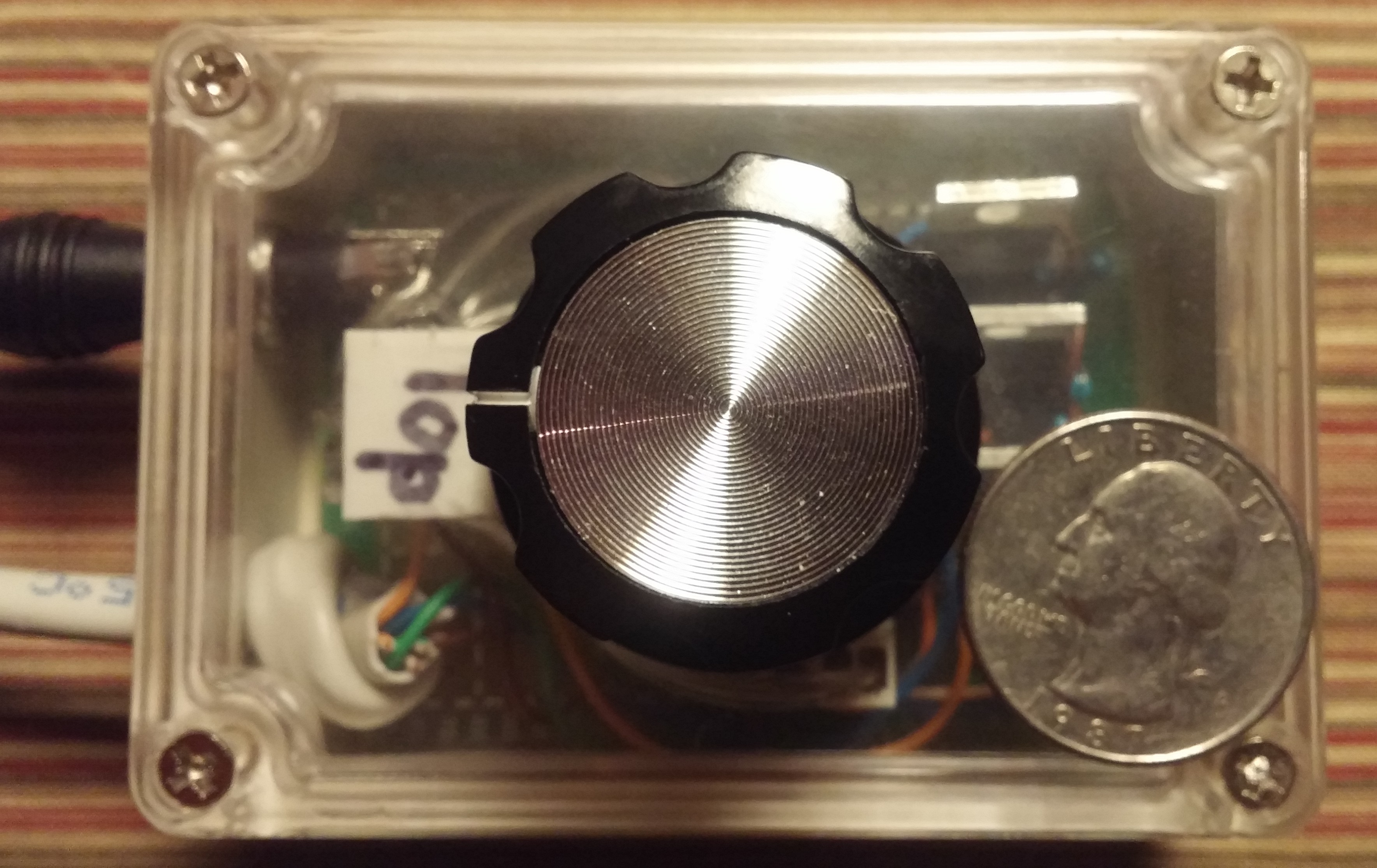
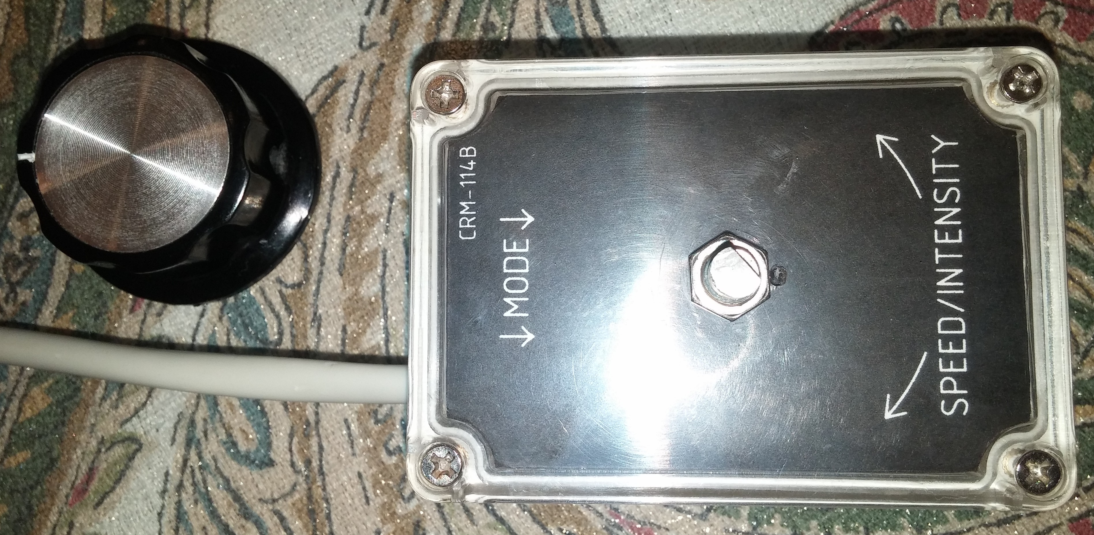
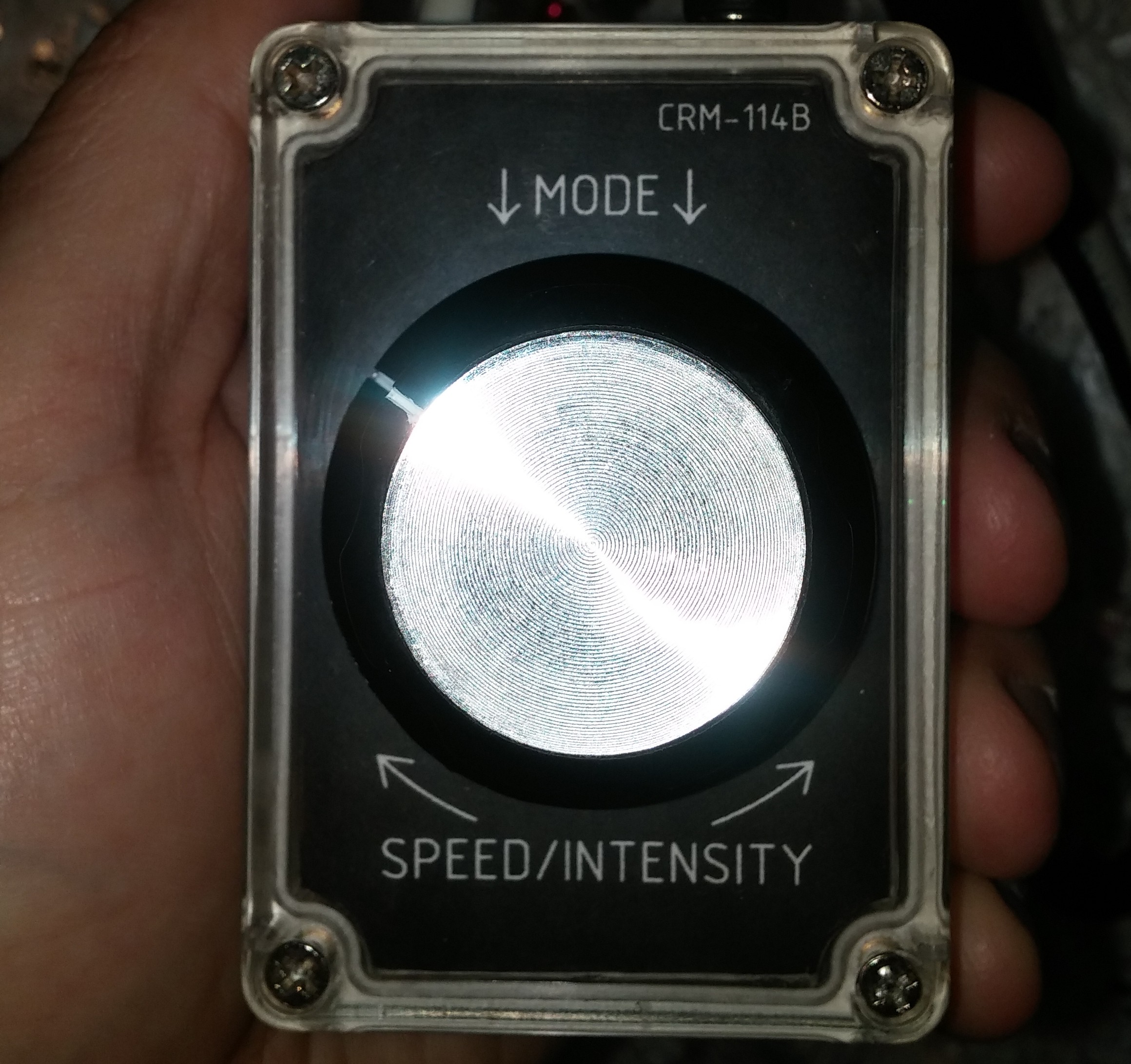
The CRM-114B has 8 light pattern modes that are controlled by the switch integrated into the rotary encoder. Pushing the knob cycles through the pattern modes.
- Random color approach mode: A pseudo-random color is chosen and each executed...

 Jean-François Poilpret
 Steve Pomeroy
 Matthias Kampa
 Alan Green