0%
0%
Custom Christmas Light Display
I've had 2 strings of GE ColorEffect LED lights for 6 years now - it's time to upgrade their controller!
 Scott F
Become a Hackaday.io member
Already have an account? Log in.
Just one more thing
To make the experience fit your profile, pick a username and tell us what interests you.
Pick an awesome username
hackaday.io/
Your profile's URL: hackaday.io/username. Max 25 alphanumeric characters.
Pick a few interests
Projects that share your interests
People that share your interests
 Andrew Bills
 ErikL
ErikL
 Grant Giesbrecht
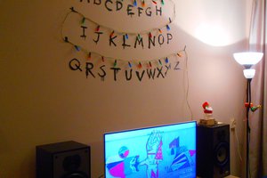
 Enrico