Close
0%
0%

CirKit

Modular software for a self designed and built 4D Printer / 6 Axis Mill using OTS hardware and reclaimed materials.

Similar projects worth following
Circuit Designer software written to create templates for routing SMD circuit boards.

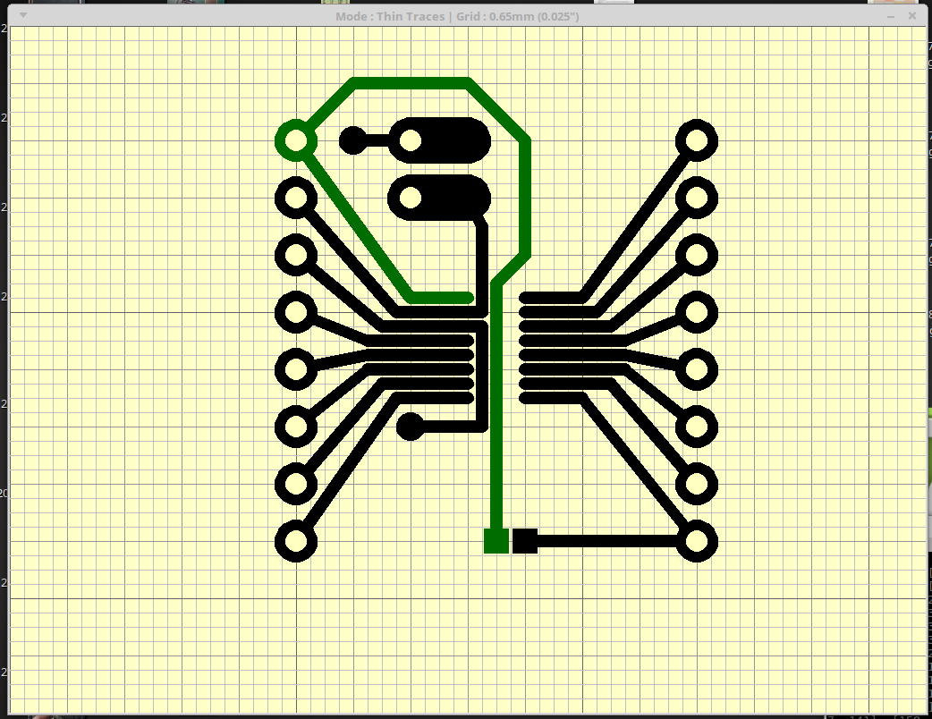
A simple circuit using an Op-Amp and variable resistance. Its a simple amplifier stage.

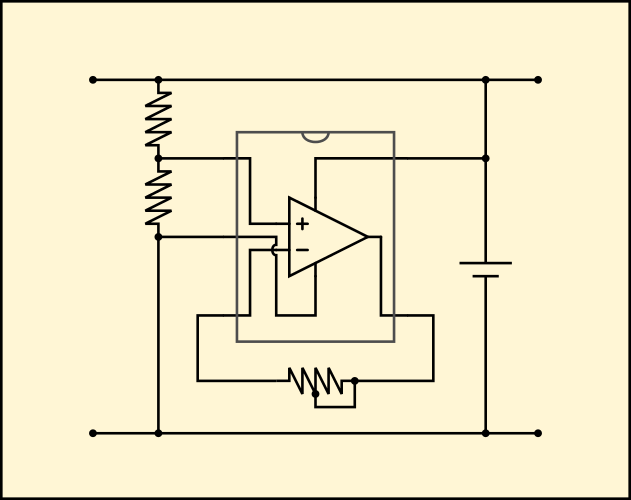
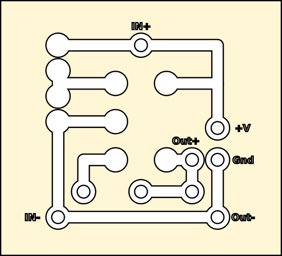
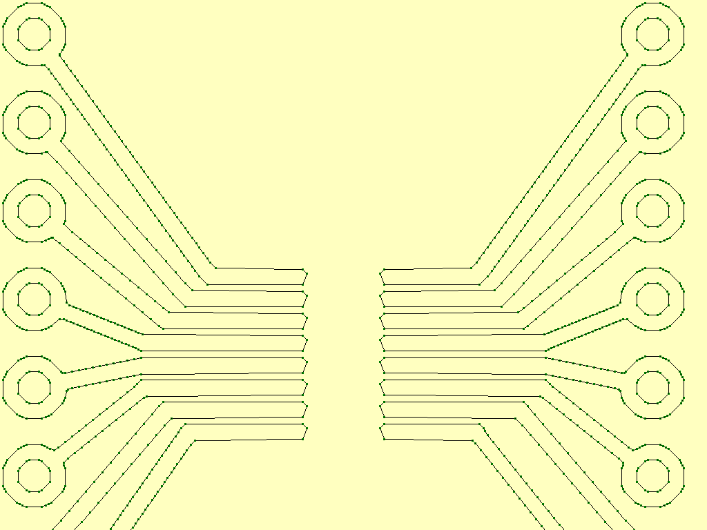
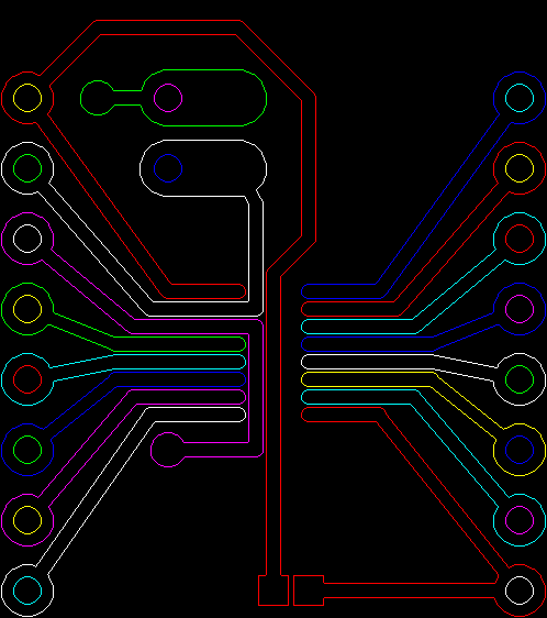
Using a simple line drawing program written in python, draw out the bones of the circuit to scale as it would appear on the circuit board and save the resulting image as a bitmap.

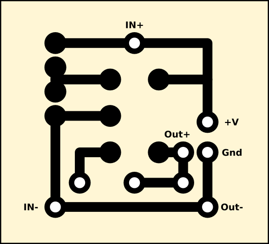
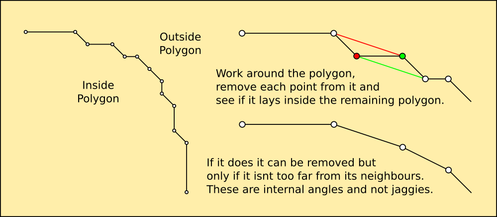
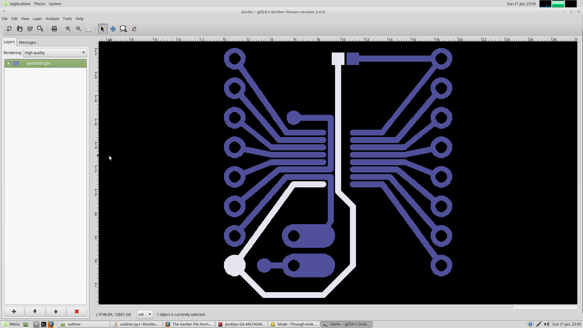
Create an outline of the image and use this to route out a line of copper, separating the track from the rest of the board and each other. The surrounding copper is left in situ for shielding.

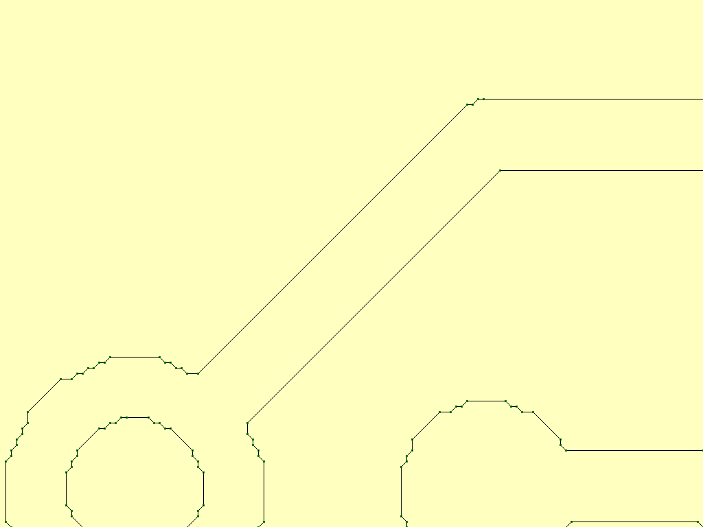
Outlining the image mathematically proved to be a real headache so I cheated slightly. By using a bitmap scaled to provide 1 pixel per stepper step and drawing from one concurrent pixel to the next, a high resolution outline can be made.

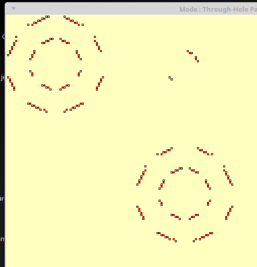
Using a technique from the image recognition in AIMOS, the picture is scanned from top left to bottom right 4 pixels at a time. Any group of pixels with an artifact in them is an edge...

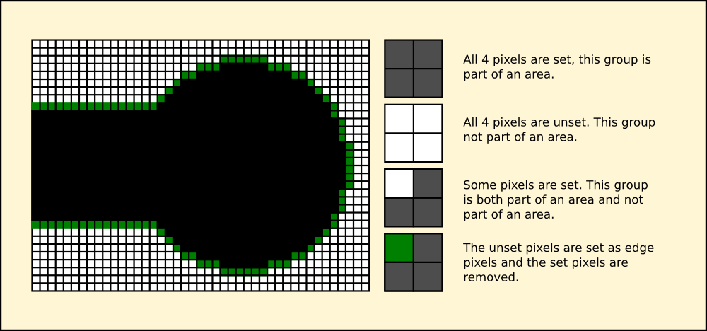
Once the routine has completed I'm left with a tuple containing only coordinates of edge pixels. These are then pulled in one by one by checking to see if each has neighbours, and adding them too. By the time all the pixels have been pulled in, the list contains the outline as an ordered sequence of coordinates.

(I'm not in the habit of commenting my code, even though I was taught to eventually at college. Bad Toad perhaps, but good code should be clear and concise so it explains itself. Not that theres anything wrong with code golf of course. But for those who cant think in code, the download is fully commented...)

def render(crd):
  global board,sw,sh,scl
  minx=1900; miny=1000; maxx=0; maxy=0
  if crd!=[]:
    for i,(x1,y1),(x2,y2) in crd:
      if x1>maxx: maxx=x1
      if x1<minx: minx=x1
      if y1>maxy: maxy=y1
      if y1<miny: miny=y1
      if i==1:
        if x2>maxx: maxx=x2
        if x2<minx: minx=x2
        if y2>maxy: maxy=y2
        if y2<miny: miny=y2
    minx=minx-20; maxx=maxx+20; miny=miny-20; maxy=maxy+20
    sw=int(maxx-minx)
    sh=int(maxy-miny)
    board=pygame.Surface((sw,sh),depth=24)
    whi=pygame.Surface.map_rgb(board,(255,255,255))
    bla=pygame.Surface.map_rgb(board,(0,0,0))
    red=pygame.Surface.map_rgb(board,(255,0,0))
    yel=pygame.Surface.map_rgb(board,(255,255,0))
    pygame.draw.rect(board,(0,0,0),(0,0,sw,sh),0)
    for i,(x1,y1),(x2,y2) in crd:
      if i==1: rline((x1-minx,y1-miny),(x2-minx,y2-miny))
      if i==2: rpad((x1-minx,y1-miny),[0.8,0])
      if i==3: rpad((x1-minx,y1-miny),[1.0,1])
    neblst=[]
    pix=pygame.PixelArray(board)
    for y in range(sh-1):
      for x in range(sw-1):
        if (pix[x,y]==whi and pix[x+1,y]==bla): neblst.append((x+1,y))
        if (pix[x,y]==bla and pix[x+1,y]==whi): neblst.append((x,y))
        if (pix[x,y]==whi and pix[x,y+1]==bla): neblst.append((x,y+1))
        if (pix[x,y]==bla and pix[x,y+1]==whi): neblst.append((x,y))
    pygame.draw.rect(board,(0,0,0),(0,0,sw,sh),0)
  for (x,y) in neblst:
    pix[x,y]=red
  pix=None
  pygame.Surface.blit(screen,board,(0,0))
  pygame.display.flip()
  sleep(3)
  return [neblst,sw,sh]
Finally the redundant coordinates are removed - I only need the beginning and end of each line to send to the mill as GCode.

Make a destination list to put the start end ends into and get the first source coordinate. It will always be the top leftmost pixel in the list after any others are transferred into the destination.

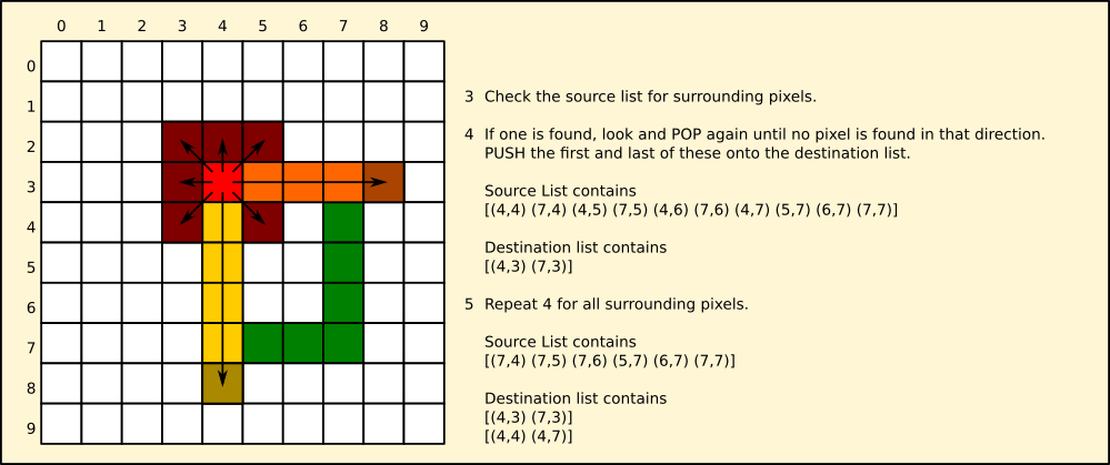
Scan for a line of pixels, take the first and last in any line found and put them into the destination list.

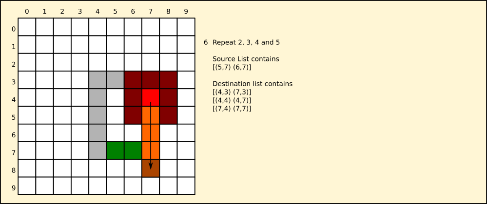
Keep doing this until there are no more pixels...

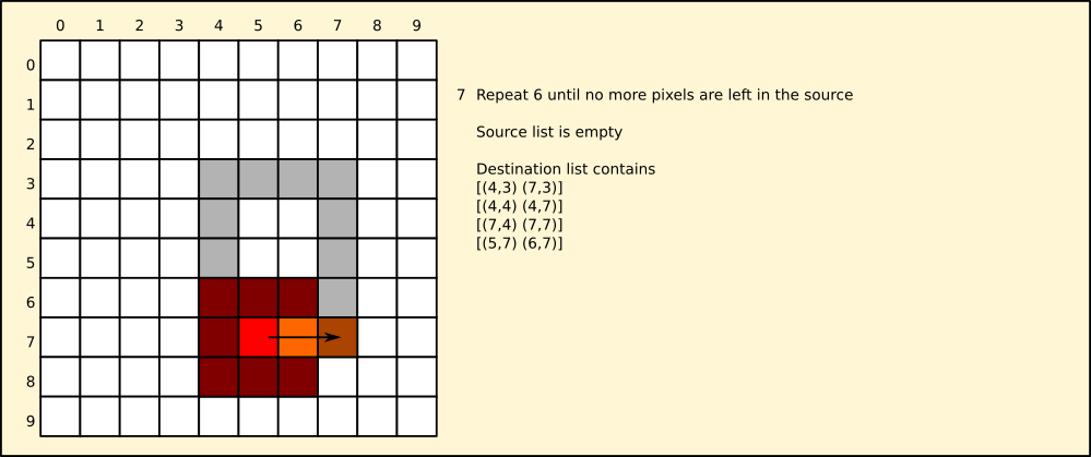
Eventually the source list will be empty, and the destination full of pairs of pixels.

def trace(crd):
  
  def nebscan(nebs,dctn):
    fnd=[]
    if nebs!=[]:
      srch=False
      x,y=nebs[0]; sx,sy=nebs[0]
      dx,dy=dctn
      while not srch:
        if (x+dx,y+dy) in nebs:
          fnd.append((x+dx,y+dy))
          x=x+dx; y=y+dy
        else:
          srch=True
      if x!=sx or y!=sy:
        fnd.insert(0,(sx,sy))
      return fnd
    
  coords=[]
  orphans=[]
  done=False
  
  while not done:
    lst=nebscan(crd,(1,0))
    if lst==[]: lst=nebscan(crd,(-1,0))
    if lst==[]: lst=nebscan(crd,(0,1))
    if lst==[]: lst=nebscan(crd,(0,-1))                   
    if lst==[]: lst=nebscan(crd,(1,1))
    if lst==[]: lst=nebscan(crd,(-1,-1))
    if lst==[]: lst=nebscan(crd,(1...
Read more »

Zip Archive - 86.32 kB - 07/08/2017 at 08:28

Download

cirkit.py

CirKit code fully commented

x-python - 19.55 kB - 01/13/2017 at 11:13

Download

  • Smooth Monolithic Outlines

    Morning.Star01/23/2018 at 23:57 0 comments

    Although the mill will take care of the jagged edges left by the bitmap and smooth them off a little they will look awful with OSHPark's precision etching, so I decided to add a smoothing routine.

    I tried a routine that checked the angles and tried to conform the points to an average but this made a pretty awful mess and I decided not to continue, and looked instead at reducing the edge pixels. it pretty soon became apparent that I could just remove those that are inside the polygons.

    After a bit of tinkering I managed to write a rule that works the same as the edge detection routine. These are both Maxwellian and step along a path in units, and eventually loop back to the start where they quit having nothing to do. They work in a similar manner to catalytic enzymes unzipping proteins, breaking only the bonds they can reach and moving along the molecule in steps.

    It still has a few problems identifying points that should be there, but it gets most of them.

    The resulting polygon looks quite tidy really considering it started life as a hexadecagon, approximated by the pixels used to represent it, and then reconstructed from the mess. I can use this technique in AIMos and Cardware too, making the vision system resolution independent. It extracts the mathematical curve described by the pixels so it can be scaled like a vector and redrawn at a different resolution.

  • CirKit 2 - KikAss

    Morning.Star01/22/2018 at 07:27 0 comments

    I've tried three times now to install KiCad on my machine, but it doesnt want to know. I've bought a new hard drive and installed the latest Mint on it since but to no avail. There's a dependency in the component library that breaks, and I cant find it, so although KiCad runs it's useless unless I draw everything by hand.

    The hell with that, I reasoned, it would be easier to write my own.

    When I joined HaD I'd already half-built the mill and written some quick software to do the job I wanted, however exposure to the modern industry changed all that. Well what with Obsidian and all I decided not to start any new projects, and take a bit of a break from hacking. You cant keep me off a computer for more than two minutes tho.

    Here's what boredom made :-)

    KikAss is written entirely in Python and uses PyGame for the display and interface, but the rest is completely self-written.

    To create decent circuits I needed an editor. It's a little basic but it works and has all the features you'd expect.

    • Undo from version 0.1b, LOL Microsoft.
    • Cut and Paste from version 0.1b, LOL Apple
    • Installs and runs on the Big Three natively, LOL KiCad
    • Its Free! Lol Eagle
    • It produces Prints, Bitmaps, GCode and Gerber natively, LOL most everything else

    Looks something like this...

    A multi track board with drilled pads and microscopic chip header for the current generation of chips.


    The board is designed by clicking and dragging thin traces, which are then terminated by pads by clicking on a pad in the Menu and then clicking the ends of the lines. Quick and easy...

    It produces a bitmapped image of the circuit design, which can be dumped on any printer. I need to work on the scaling, printers are a total mishmash of designs and this wont be easy.

    Now for the clever part. OSH expect their circuits to be Gerbers, and my mill expects GCode. There had to be a halfway house between the two, and this is it. A routine to convert a bitmap into a GCode coordinate string. Gerbers are also coordinate strings but they are more complicated, so whats needed is an outline of each track, which is then traced to create polygons from the edges.

    Here each polygon is drawn in a different colour. At the moment they are lists of pixels describing each outline.

    And after tracing...

    Lists of coordinates generated from the centres of the edge pixel coordinates and interpolated to remove the interstitial points, leaving just the corners.

    After a monumental session crashing the hell out of GerbV, I finally figured out the Gerber format well enough to create one from scratch.

    I still have problems, trace 1 is always opaque, and although it has a transparent cutout on it, it is always filled in. I dont know why, and the layers in the file look ok too.

    Ahah you say, its upside down too! Yeah, thats what I thought at first, but logically speaking this would be layer three of six, face down and sandwiched in between a solder mask and another copper layer, which would be face up. I'll have to experiment with this, because I've never produced artwork for OSH, or any board maker come to that.

    I would expect OSH to want the Gerber to have its layers in order top to bottom, oriented as they are in the final board, thats how I've seen others produce their artwork. So by using this geometry it should work out ok. GCode is fed to the mill with the copper face-up, so is oriented correctly for that in any case - but because it is designed to drive custom hardware, it can be flipped in any direction by the mill's software settings. It uses a RepRap controller with the standard software, but swaps the heater for a hot air nozzle, and the driver for a cutting head, and also adds a solderpaste dispenser designed to take those syringes you can buy off eBay. I've done a bit of experimenting already, and the solderpaste I have is too thick to go through a syringe...

    Read more »

View all 2 project logs

Enjoy this project?

Share

Discussions

ActualDragon wrote 01/10/2017 at 13:07 point

a 4d printer? how does that work?

  Are you sure? yes | no

davedarko wrote 01/10/2017 at 13:41 point

you'll send the commands into the past and the printer is done as soon as you hit print, of course.

  Are you sure? yes | no

Morning.Star wrote 01/10/2017 at 14:27 point

Nice. :)

Dont be giving me ideas though...

  Are you sure? yes | no

Eric Hertz wrote 01/11/2017 at 04:37 point

Awesome!

  Are you sure? yes | no

K.C. Lee wrote 01/11/2017 at 06:05 point


Can't resist.

  Are you sure? yes | no

Morning.Star wrote 01/10/2017 at 14:27 point

Heh, thats "4D", meaning it prints in a dimension not accessible to a traditional 3D printer...
Normally
the nozzle points into the bed at 90 degrees. I've added two extra axes
of movement on the nozzle so it can print at any angle relative to the
bed. This was a revelation after I'd converted the Reprap into a basic
mill and wanted to make it more capable, I designed the binnacle to hold
the router and motor and realised the print head would fit in it rather
than replace it while printing.
It means the printer can do tough prints and print onto existing items with a little work.

Thanks for the interest.

  Are you sure? yes | no

ActualDragon wrote 01/10/2017 at 15:35 point

alright, that makes more sense, the memory of when we went to a 4d theater kept coming to mind

  Are you sure? yes | no

Similar Projects

Does this project spark your interest?

Become a member to follow this project and never miss any updates