BASIC PRINCIPLE :
Master generates an one-directional signal. The slaves use the signal as a data source and for power suply as well. The signal consists of all 256 8-bit characters coded in one 256-bits string which is repeatedly transmitted on the Signal wire in an infinite loop.
Hexadecimal expression of the string:
440C377B050919296DFE8385954C4D456B1A3A4E5C5E3C87CCD9DA7ABAFB9F80
There is a high "measure"-impulse between every two bits for the evaluation purposes and better power supplying capability.
So the string :
01000100...
looks like this practically:
0111010101110101...
The second wire is bi-directional and is called Response. It is low normally but it goes high when a switch is pressed in order to start the communication with master. If Response is already high that means there is an ongoing communication with another slave. The level is set low when the Slave_ID is found. If there is required a state change of an actuator, Response is set high by master immediatelly and remains high until the programmed Slave_ID ( actuator ) is found:
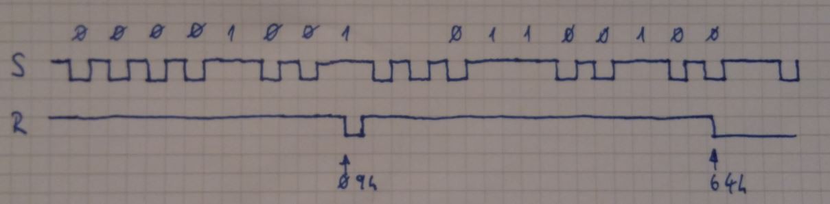 An example for Slave_ID 0x09 which causes a state change of Slave_ID 0x64. Response is driven high first by slave then by master.
Third wire is GND.
FUNCTIONS :
( currently ) three actuator functions can be assigned to the slaves:
- LED_On
- LED_Off
- LED_toggle
PROGRAMMING GUIDE:
The master's controller ATmega8 is connected to 2 x 2 digits 7-seg. displays. First 2 digits shows the EEPROM address, the second two digits the data stored at the displayed address. There are three buttons : +, - ( or Up and Down ) and Enter. It can be moved inside the entire EEPROM by + and -. The higher half - 100h to 1FFh is indicated by the decimal point. If Enter is pressed the stored data value can be increased or decreased by + and -. Enter pressed once more - new data is stored and the control goes back to the address. For the change from programming mode to operation mode it must be written 00h at the address 1FFh. Press + and - together to jump back to the programming mode. In operation mode is nothing displayed, except the decimal point when the Response is driven high.
At the address 1FFh the bus speed can be set - theoretically in the range of 01h to FFh ( but practically it makes sense only till 7Fh, above 80h it runs very slowly and the resolving process is not reliable ).
Following bytes are necessary for the functionality:
| Range | Usage |
| 000h - 006h | 7-seg characters* |
| 007h - 02Fh | constants for the signal construction* |
| 040h - 04Fh | Channels for the actuator functionality LED_On |
| 050h - 05Fh | Channels for the actuator functionality LED_Off |
| 060h - 06Fh | Channels for the actuator functionality LED_toggle |
| 100h - 1FEh | Slave_IDs where can be stored the pointers to function or the state (in case of actuator) |
| 1FFh | 00h - Entry point to Operation Mode, Range 01h - FFh = frequency change |
1. Example:
given slaves - Switches : ID DDh, A5h Actuator ID 44h
to do : If the switch with ID DDh is pressed --> Actuator with ID 44h - LED_On, if the switch with ID A5h is pressed --> Actuator with ID 44h - LED_Off
Solution:
EEPROM settings : 040h - 44h, 050h - 44h, 1DDh - 040h, 1A5h - 050h. At 144h the current status of the actuator will be stored by master.
2. Example:
given slaves - Switch : ID DDh, Actuator ID 44h
to do : If the switch with ID DDh is pressed--> Actuator with ID 44h - LED_toggle
Solution:
EEPROM settings : 060 - 44h, 1DD - 60h. At 144h the current status of the actuator will be stored by master.
CONSTRUCTION DETAILS :
As written, Signal is generated by master and distributed by a single pin in this case. This project is presented with 3 slaves ( 2 switches and 1 actuator ) in order to fullfil the 1 kB limit but I've tested it with 8 slaves ( 5 switches and 3 actuators ) and it worked ok because all slaves are in Power-down. In case of more than 20 slaves it should be considered a power supply solution with better performance.
All codes can be assmbled by AVR/Atmel Studio.
MEMORY USE CALCULATION :
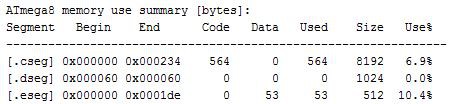
Master :
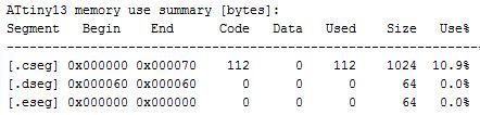
Slaves :
Switches DDh, A5h
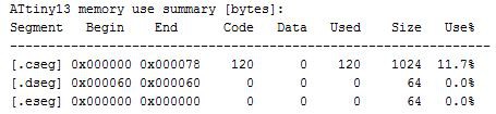
 Actuator
...summed up:
| Device | bytes |
| Master - flash | 564 |
| Master - EEPROM | 53 |
| Slave Switches 2 x 112 | 224 |
| Slave Actuator | 120 |
| TOTAL | 961 |
* REMARK: DO NOT EDIT THE BYTES IN THE RANGE 0x000 - 0x02F, IT CAN CAUSE DEFECTED FUNCTIONALITY AND/OR NOT READABLE 7-SEG. CHARACTERS.