 M.daSilva
The driver boards are designed as a repeatable way of easily interfacing a Nixie tube with a microcontroller... I have to be able to quickly have a bunch of them available without too much fuss. I won't say the same for this main board; I'm too impatient to design a one-off board, wait three weeks, I want my display NOW!
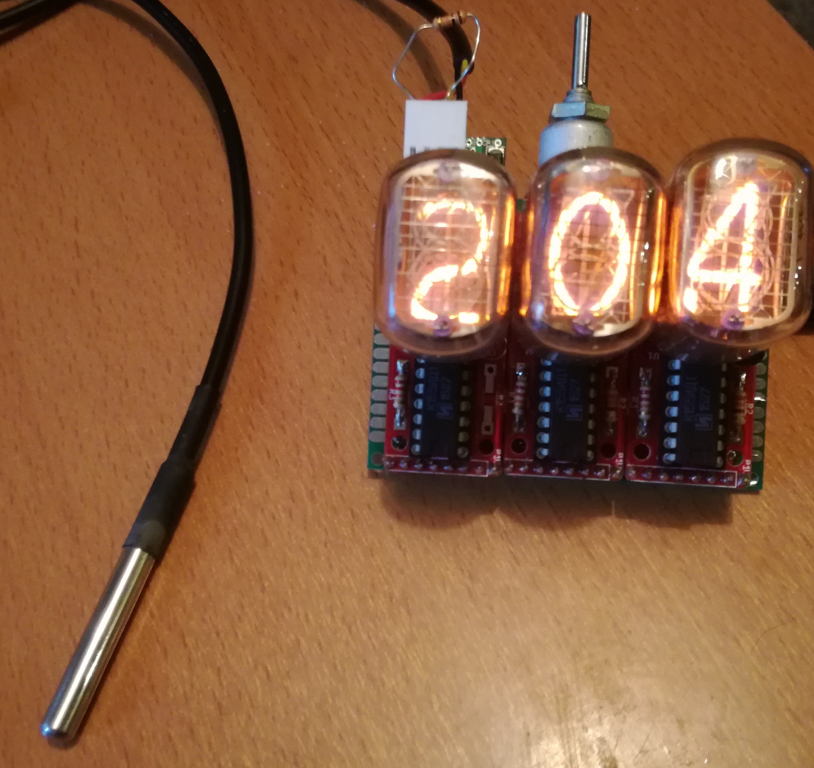
Three Nixie driver boards were used: one without decimal point (with an IN-12A tube), two others with decimal points (with two IN-12B tubes). With those, I'll be able to display values from 0.00 to 9.99 with two decimal digits, 10.0 to 99.0 with one decimal digits, and 100 to 999 without decimal digits. It seems to be the best compromise to me.
A simple ATMega328 doesn't have enough (or barely enough) pins to directly send signals to the three drivers+the two decimal digits+the sensors... I used two cascading shift registers (74HC595) to reduce pin usage. Queue the big mess of wires.
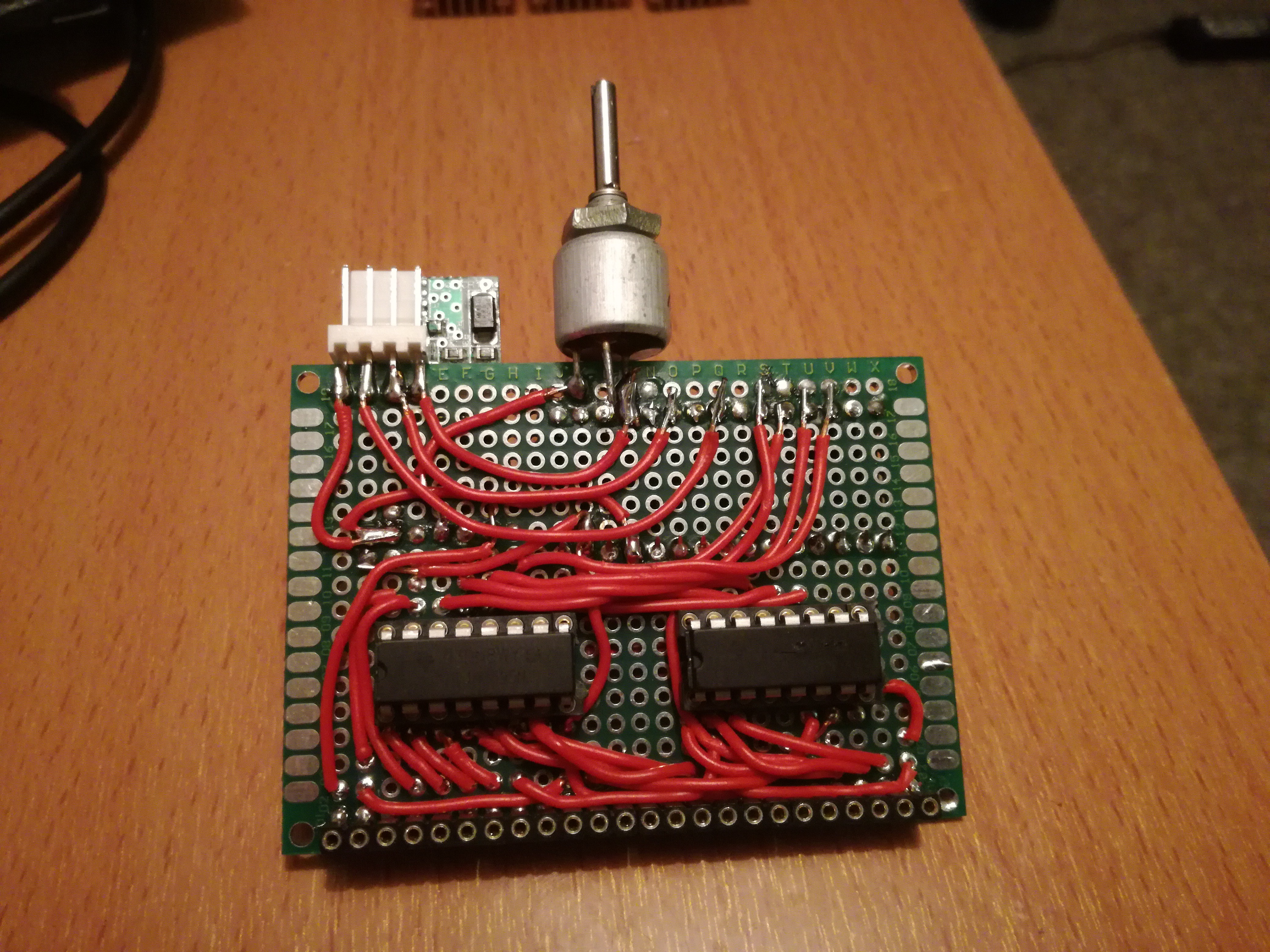
The two first digits (i.e. 4 data lines each) were connected to the first shift register, the last one (along with the two decimal points) was connected to the second register. The serial, data, clock and enable line were then connected to the microcontroller.
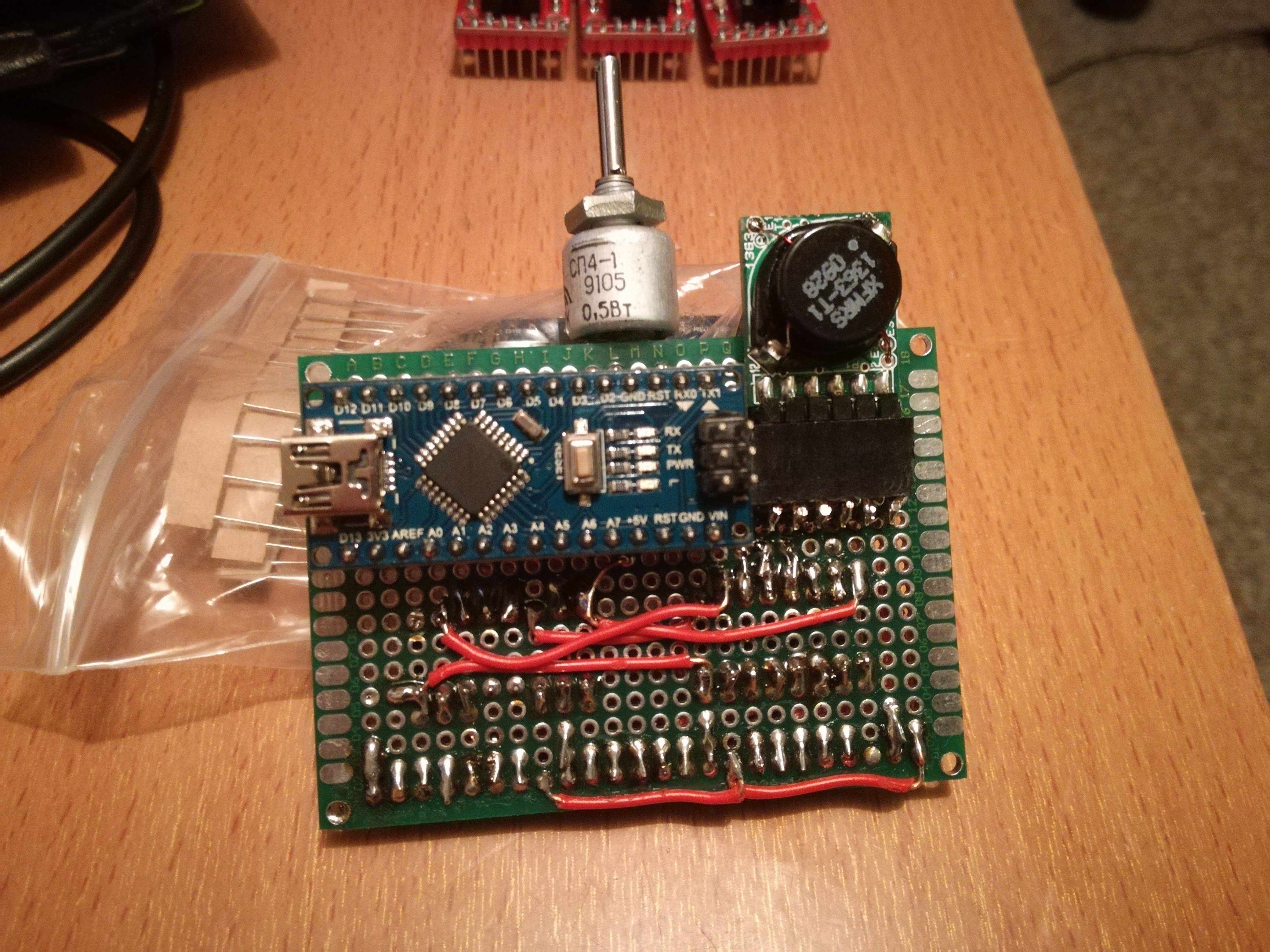
The high voltage power supply (1363 model from Taylor Electronics) is connected on the other side, along with the ATMega328 controller. The potentiometer sets the PSU voltage, and a 4-pin connector allows to connect the sensors (two data lines, 5V and GND).
I first tried a DS1820B temperature sensor... The temperature (in °C) seems to be correctly displayed. For negative values, I made the display blink for 50ms.
I need to make a case for this!
Discussions
Become a Hackaday.io Member
Create an account to leave a comment. Already have an account? Log In.