 agp.cooper
Noisy Regen Simulation
Alan Yates (http://www.vk2zay.net/article/128) has stripped down the Franklin Audion circuit to its basics and taken the audio off the emitters rather than the tuned circuit. This seems to make more sense to me:
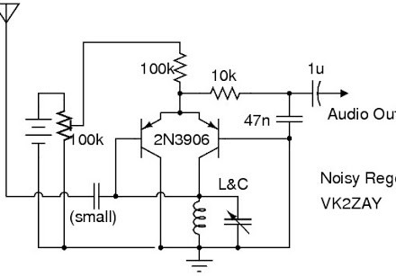
(Note that the 47n output filter capacitor should be 4.7n!)
So I stripped my circuit down and was able to get the simulation to honour the expected frequency locking and demodulation:
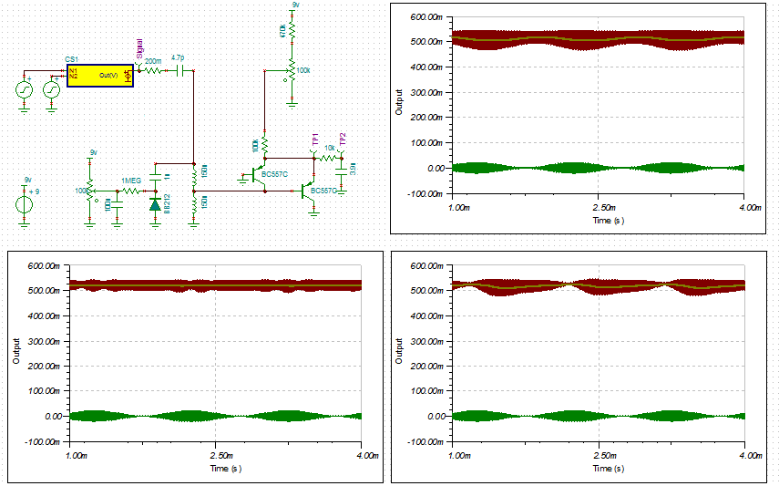
- on frequency and in lock
- off frequency but still in lock
- off frequency and out off lock (i.e. beating).
The green is the input signal, the red is the oscillator and the yellow the output audio.
Note how the oscillation can be quenched in case 2.
---
Now that I have a working simulation I can test component values. Or in this case the component value the 100k emitter resistor. You may have noted I increased the value from 10k R to 100k R in this version. The results indicate that the same operating point can be found with the 10k resistor as the 100k resistor. The main difference is that the oscillation amplitude can be much higher (the full available collector voltage or about 0.7v pp) and consequently the available mixer gain (i.e. higher audio output). This is reflected in actual use. The oscillator frequency also shifts with higher oscillation amplitudes.
Using the higher (i.e. 100k R) emitter resistance will tame the receiver. Audio gain is best found elsewhere.
---
Added the schematic to help show how the oscillator works:
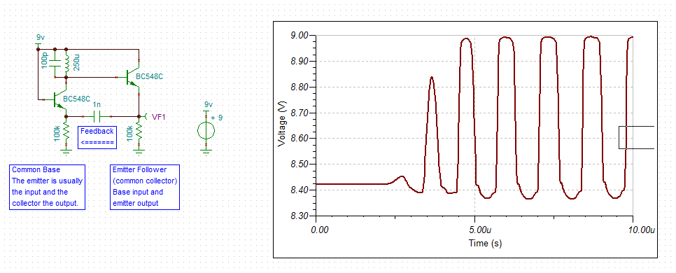
I have used NPN transistors (as this is what most people are used to) and split the emitter resistor to show the two transistor amplifiers.
---
Here is the updates strip-board design:
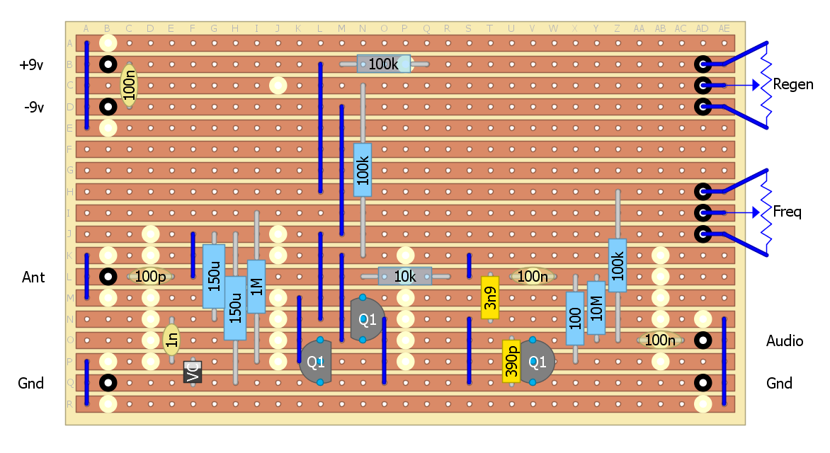
If you are interested, the input impedance of the Franklin oscillator in this circuit is about 1.2k (approximately that of the coil impedance tap) and the output is about 10k (approximately the same as the low pass filter).
----
Lumped Inductors - How Good?
Although I have had success with the lumped inductors, I know the Q is quite low.
But how good or bad are they? That depends on the wire diameter and core material.
An Internet search suggests that they roughly match the Vishay IRF-24:
- L = 150uH +/-10%
- R(dc) = 4.2 vs 4.9 (Vishay)
- I(dc)= 175 mA vs 150 mA (Vishay)
- Q = 60 (Vishay)
- Self resonance = 4.75 MHz
Now a Q of 60 is far less than 300 to 500 you can get with an air coil.
For MW (i.e. 1 MHz) a Q of 60 translates to an unloaded bandwidth of 17 kHz.
Which is why they work in this application although not great when the coil is loaded.
Alternates
The alternates are:
- Air coil - conventional (very good but not suited to a PCB).
- Air coil - spider (very good but not suited to a PCB).
- PCB coil - Low Q (~40-70).
- Ferrite beads (mix 43) - small but low Q (~8!).
- Iron powder toroid (mix 1 or 2) - high Q but bulky for 200uH.
- Ferrite toroids (mix 61) - medium Q.
- Ferrite rods (mix 61) - medium Q but large.
I have designed and built MW radios using the first four options.
Using the data from an Amidon datasheet for their mix 61, the maximum Q is about 270 (between 1 MHz and 2 MHz). This is the best ferrite material for MW frequencies.
Options not tried:
- I have a T-200-2 mix 2 iron powder toroid that with 144 turns of 22 or 24 AWG would work well (Q>>200?).
- A FT-50-61 with 50 turns of 26 or 28 AWG should work okay (250 uH) and pretty small.
- A ferrite rod cut to fit the board width (say 2") and 60 turns of 22 AWG (0.63 mm diameter) wire (4 cm long) would be the same. I have a 15 cm long by 1 cm diameter mix 61 ferrite. The ferrite rod can cut (not sure how yet) and attached to the board with plastic screw-down cable clamps.
Option 2 seems to be the best for a PCB mount but the toroids are a few weeks away (just orded them on ebay).
AlanX
Discussions
Become a Hackaday.io Member
Create an account to leave a comment. Already have an account? Log In.