 Rene
ReneProject Goals
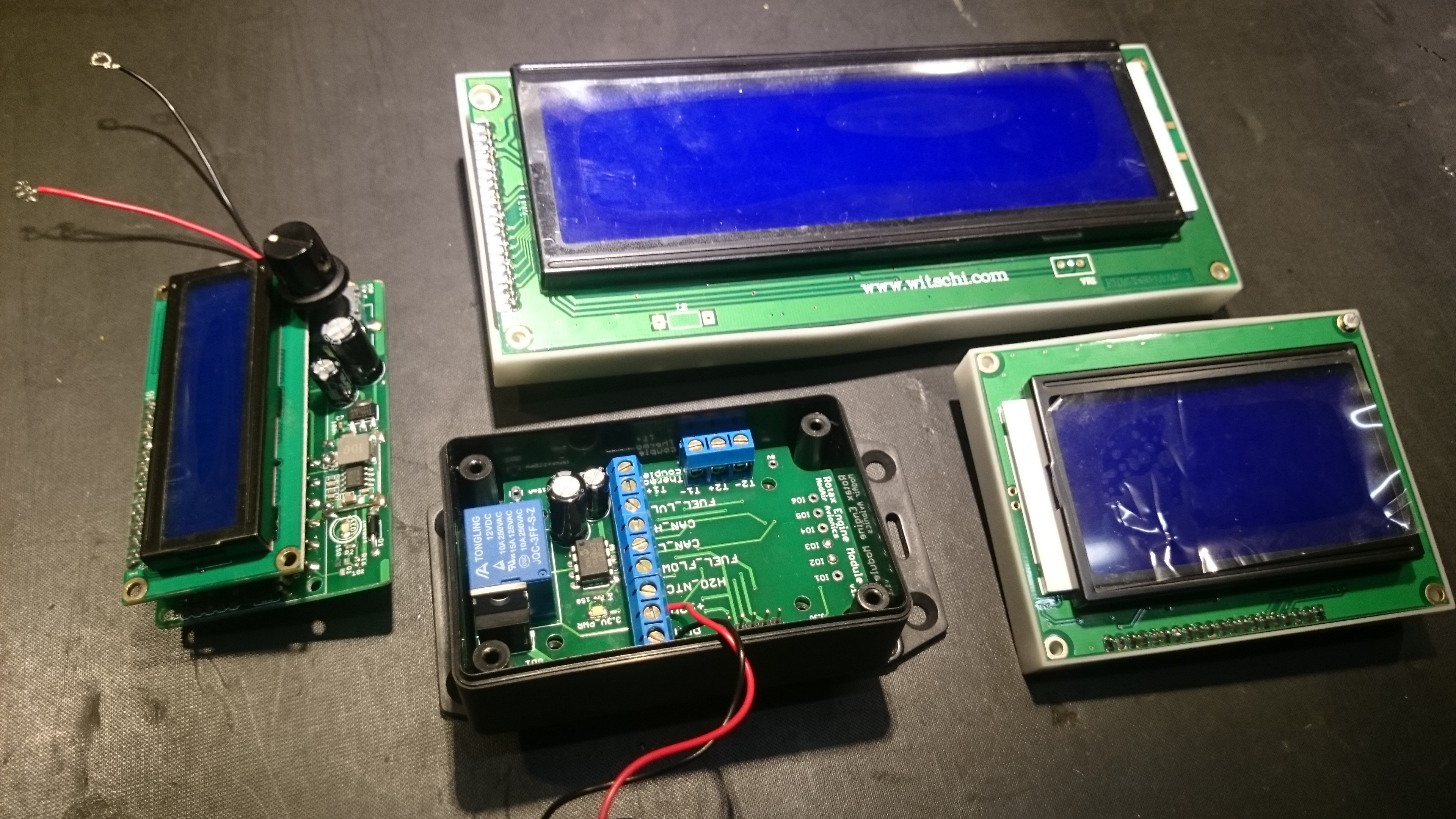
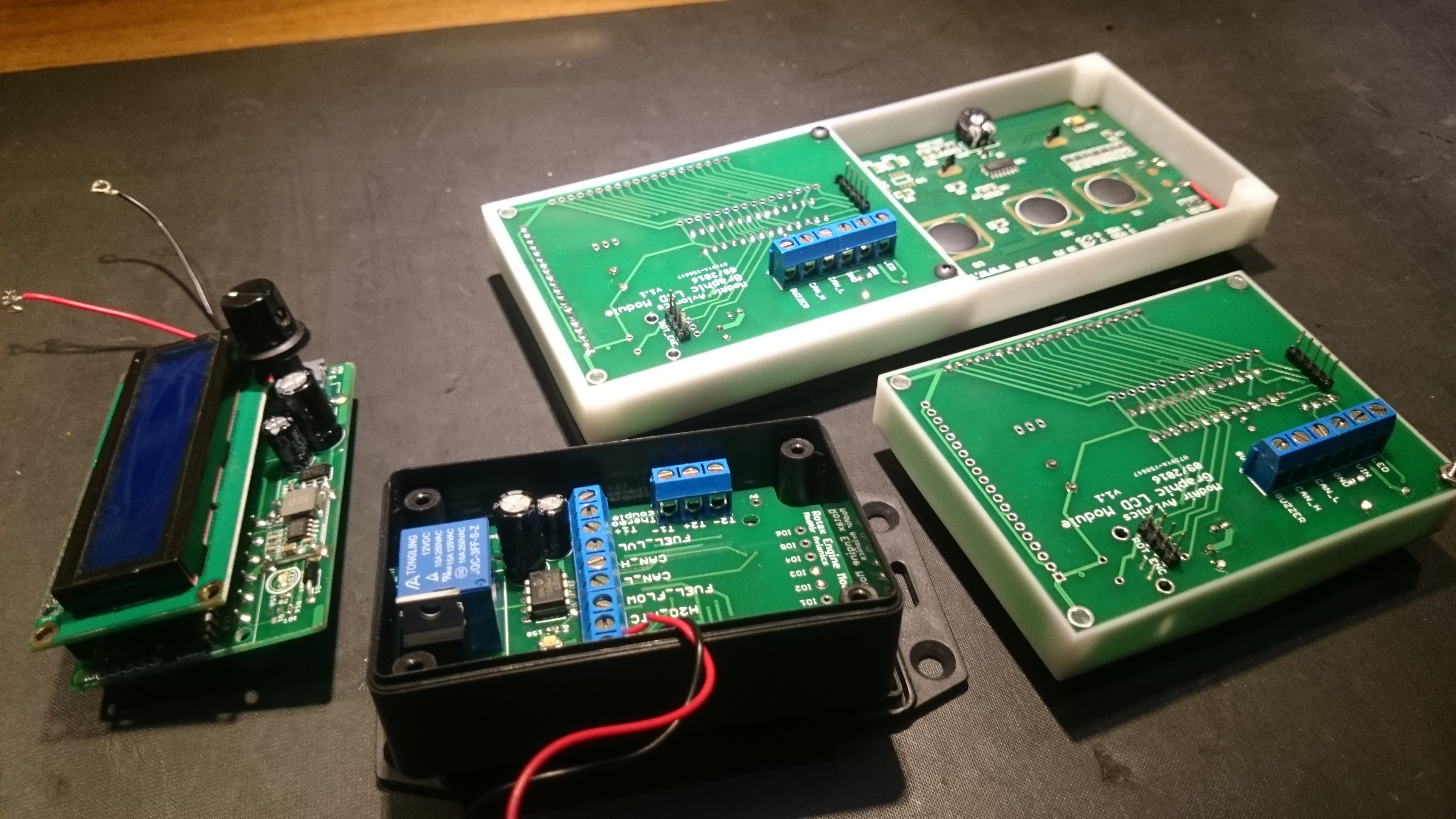
The main goal of this project is to supply an open source infrastructure for avionics development. Each aircraft has different budgets and requirements for aviation instruments; trying to address them all with a single module is unrealistic. A modular approach splits functionality into reusable components. This makes it easier to maintain, replace faulty units, and upgrade by adding modules instead of replacing the entire system. An example is shown below:

Another advantage of the modular approach is that the project can be completed in stages, with nice-to-have features being added later. As a pilot, having access to real-time, reliable and relevant information greatly assists in the decision making process. Adding additional instruments thus becomes another way of making aviation safer for everyone sharing the airspace. With the centralised design of the original prototype, I needed to remove the electronics from the aircraft every time I wanted to add functionality. This resulted in not being able to fly while features were developed (which usually took longer than expected), or consequently not developing features because I wanted to fly.
The end goal is to have a library of modules that can be mixed and matched to suit different pilot and aircraft requirements. Examples of modules include:
| Module | Features | Status |
| Rotax 582 Engine | RPM, EGTs, H2O, fuel level, fuel flow, relay and open drain outputs | prototype |
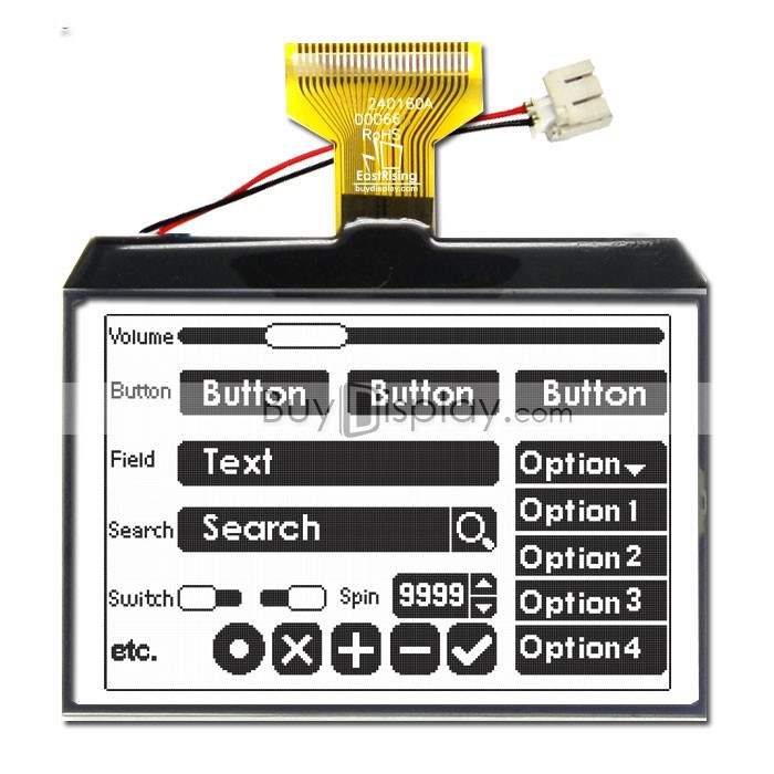
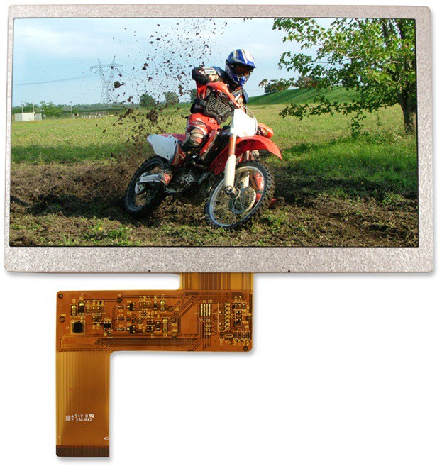
| 3.0" Graphic LCD |
Nelytech NT-G128641A 128x64 monochrome (Black on White) | prototype |
| Navigation | Waypoints, GPS, IMU, altitude, air speed | design |
| Computer Interface | Allows PCs, tablets, smart phones and smart watches to be used as multi-functional displays (MFD) | planning |
| 7" TFT LCD |
Single board computer (RasPi / BB) with sunlight readable TFT LCD screen | planning |
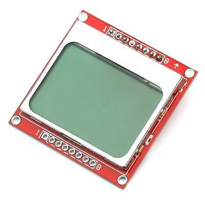
| 1.4" Graphic LCD | Nokia5110 84x48 monochrome | planning |
| Aircraft Interfaces | Outputs for fuel pump, lights, flaps, trims, heater, gear, ... | idea |
| VHF Transceiver Interface | Remote interface for airband radio | idea |
| Transponder Interface | Remote interface for ATC transponders, altitude encoder for older Mode C types | idea |
| Aircraft Intercom | Annunciation, volumes, PAX | idea |
| Situational Awareness | SDR-based ADS-B receiver, air-band channel activity indicator | idea |
| Air-to-air Communication | Low-cost ISM-band position broadcasting (similar to ADS-B in and out) to keep track of other aircraft in your squadron | idea |
| Black Box | Logging to micro SD card | idea |
| Power | Alternator and battery management, voltage and current | idea |
Personal Goals and Current Priorities
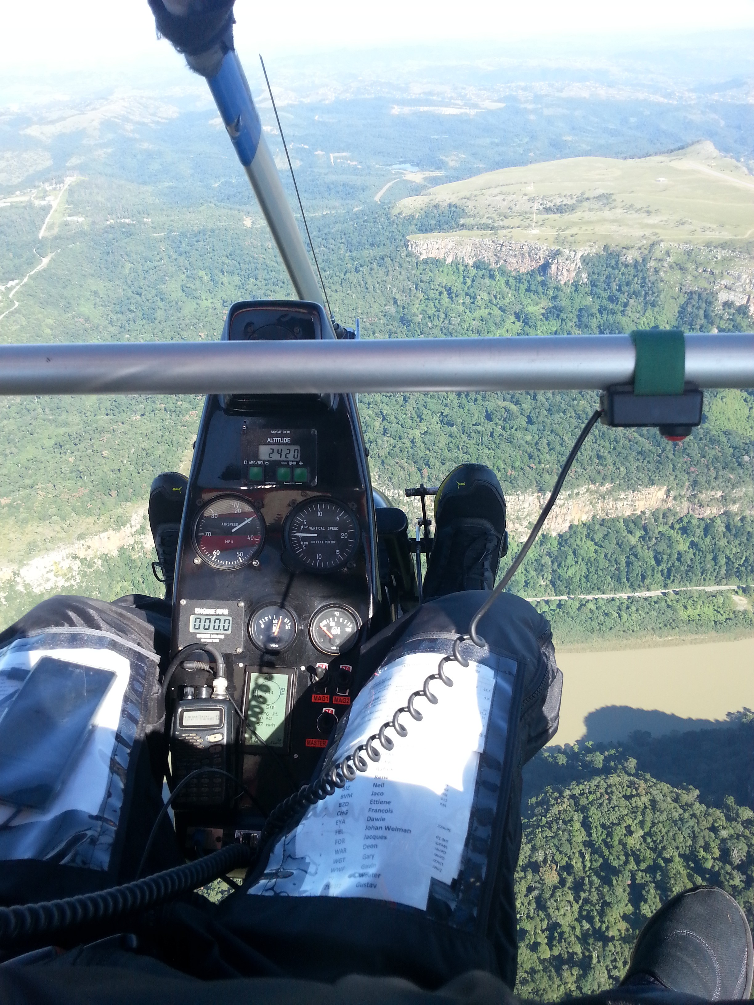
My main goal is to develop an advanced avionics system for my weight shift controlled (WSC) microlight trike (see background post). Being an open cockpit, my requirements might not always align with other pilots expectations. For example, touchscreen interfaces are almost impossible to use in-air (e.g. typing, zooming, panning); especially when fighting bumpy air and with thick gloves. Physical buttons, knobs and rotary encoders work quite well though. Depending on the angle of the sun, most TFT LCDs are challenging to read. Transflective STN LCD panels on the other hand, are easily readable in direct sunlight.
System Design
Requirements drive design. Read that again but slower. This project has three simple requirements:
- Open source: design files and source code (for hardware, firmware and software) are hosted on GitHub under the GPLv3 license. This means that the contributions to this project may not be used in any closed source projects. Anyone is free to use the code for private and/or commercial use, but needs to publish any modifications under the same open source license.
- Physically modular: modules (consisting of sensors, control outputs, interfaces, and/or displays) plug into a shared bus. Each module provides a specific set of features (also see overall feature wishlist) based on its attached peripherals. A module should be less than $100; if a set of peripherals exceeds this, the functionality should be split into smaller modules.
- Modularity in terms of software: no firmware updates should be needed if a new module is added onto the bus. All the functionality related to the new module (which might be unknown at this point in time) needs to be self-contained. Having access to all other sensor readings on each module allows for some interesting data fusion and new parameters. For example, the module that measures the fuel level can also calculate the fuel endurance and range with the current tank, based on the ground speed and average fuel consumption.
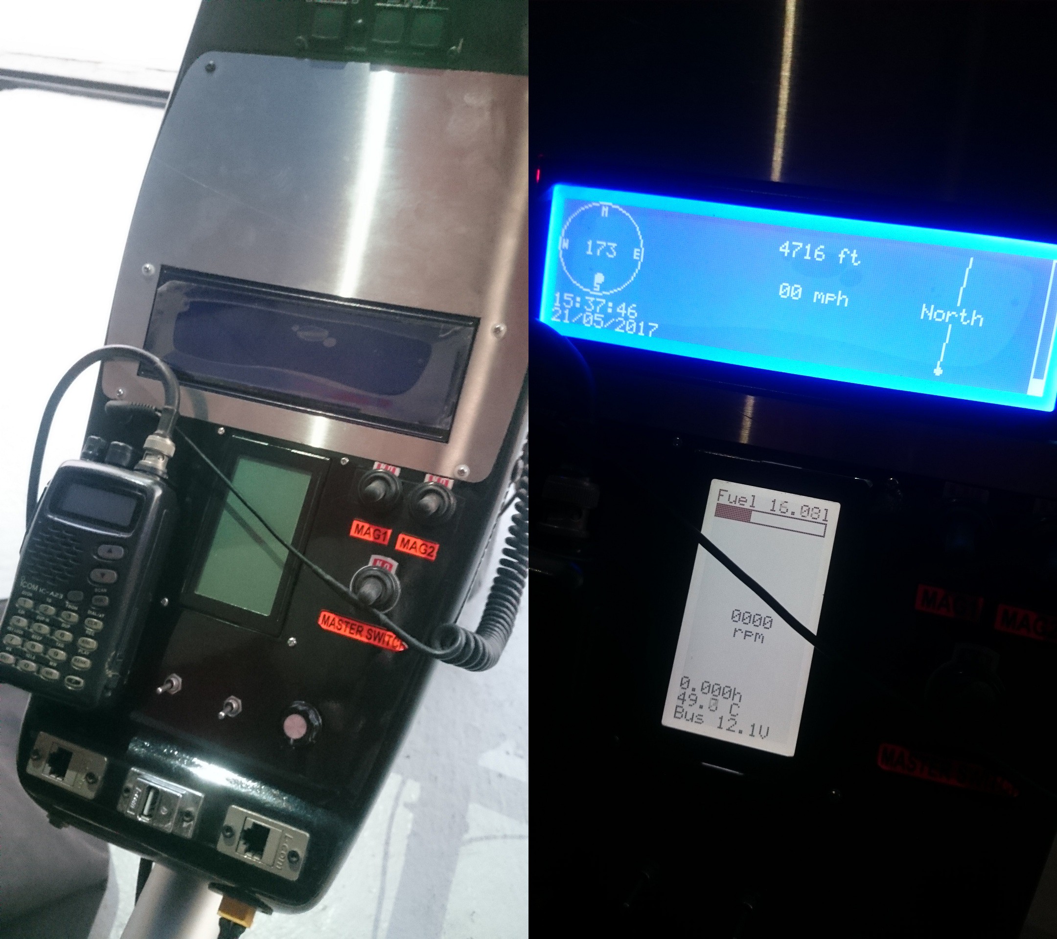
On the display modules, this modularity is achieved by allowing the user to add widgets onto the screen, and linking them with sensor parameters as shown in the diagram below.
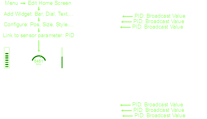
This approach applies to all display modules; whether small 2x16 character LCDs, monochrome graphical displays, Smart-phones, tablets or large colour TFT LCD screens. Widgets can be simple text, graphical items like gauges and bars, graphs that plot parameters (over time or against other parameters), attitude reference lines, 2D moving maps, or full 3D components such as synthetic vision (using topological maps and taking position and attitude sensor inputs).
For sensor modules, modularity is realized with a remote menu that can be accessed by a display module. This remote console can be used for configuration, alarm setup, viewing status, editing the value broadcast rate and any other options relating to the sensor.
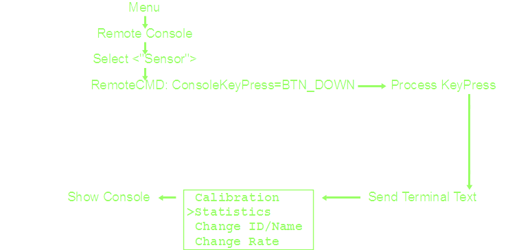
This also greatly simplifies the communication protocol.
There is no need to define message types for calibration or any other
sensor-specific data. Similarly, the display modules and rest of the system
need no prior knowledge of how to handle custom user data. User inputs can be
simple up/down/ok/... buttons, rotary encoder inputs, or any characters from a keyboard.


 matthewreed
 pavan kumar
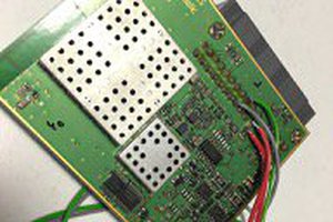
 Saabman
 JP Gleyzes
Hey Rene,
I just joined hackaday for this project. I was just tinkering up some similar thoughts as well. I'm a automotive EE by trade (HW, SW) and student pilot by heart. Would love to take part in this because I strongly believe the big age of aviation is yet to come! Anyone excited to go electric?
I'm interested in data logging and analysis ... an open-standard common CAN bus for all systems is just what a plane needs nowadays.