 Ted Yapo
UPDATE: the speeds measured here don't represent the true switching speed of these gates. See this log for more details.
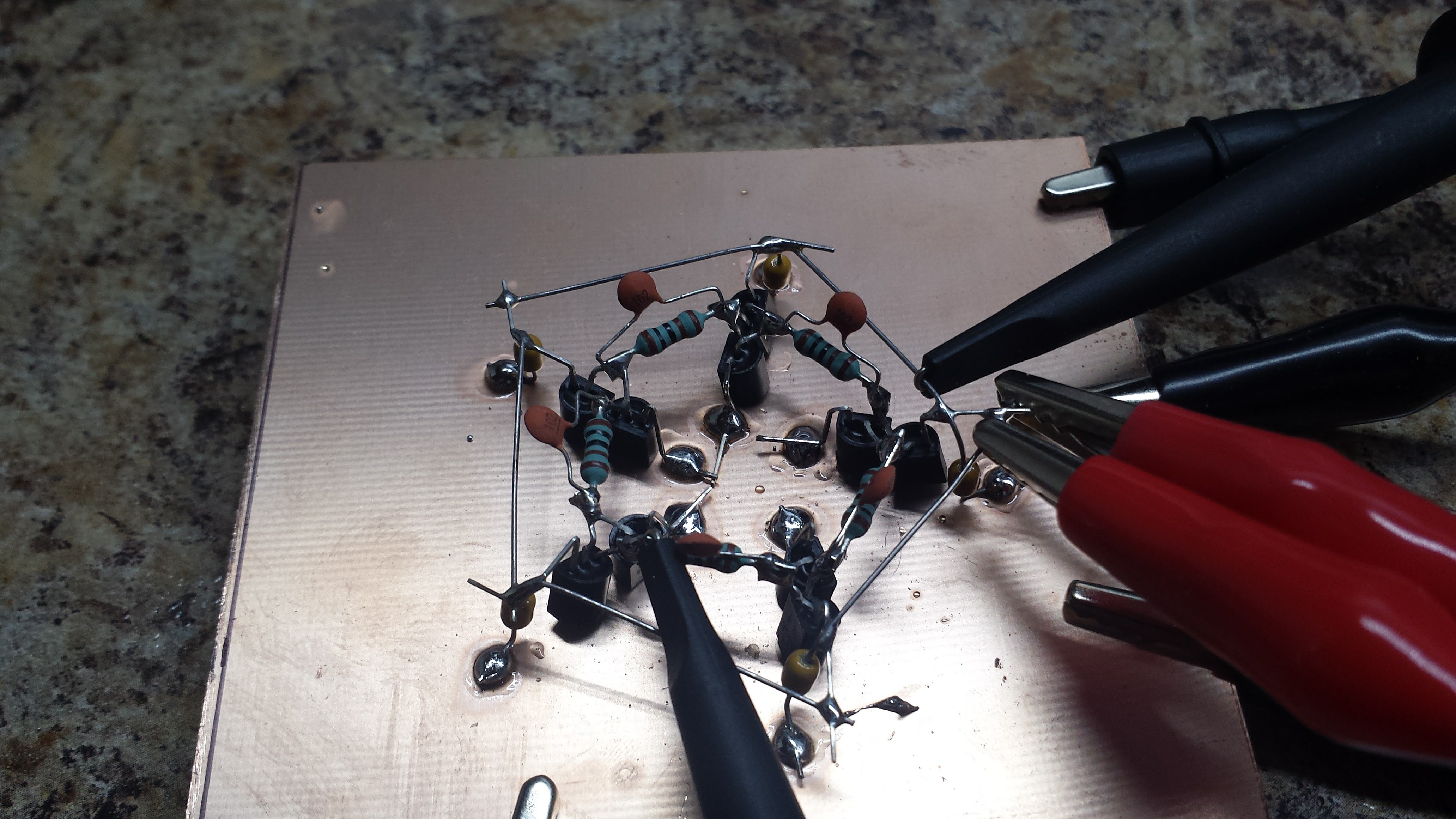
I played with the inverter simulation a bit - before testing the speed on the NAND gate, I figured I'd get things straight with the NOT. Adding the base resistors drops the power consumption as expected, but also dropped the oscillation frequency from 2.4 MHz to about 500 kHz. OK, I'll add the speedup caps. Simulations pointed to 1nF as a good value - which seemed large to me, but works OK on the board:
With the 1k base resistors and 1nF speedup caps added, I tested the ring oscillator at a bunch of different voltages. I hooked channel 2 (cyan trace) to the power lead to label the images with the supply voltage.
550 mV
Again, I saw oscillations down to about 0.4V supply voltage, but things only started to stabilize above 500 mV. Here it is running at about 5kHz.
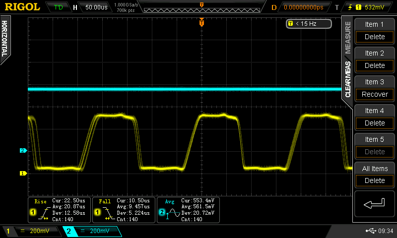
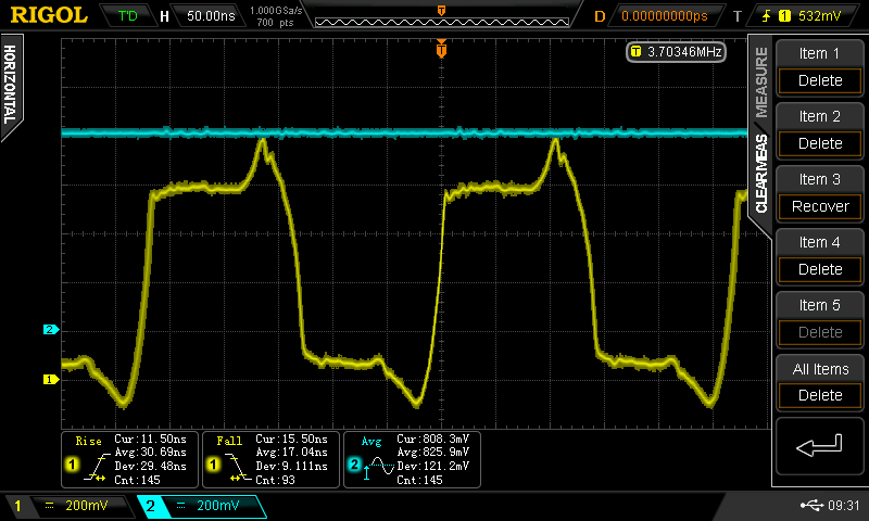
707 mV
This logic is probably only truly usable above 700mV (at the temperature I tested at - whatever that was). The circuit runs at 796 kHz, implying a gate propagation delay of 12.5 us, with a rise-time of 70.5ns (fall time not captured).
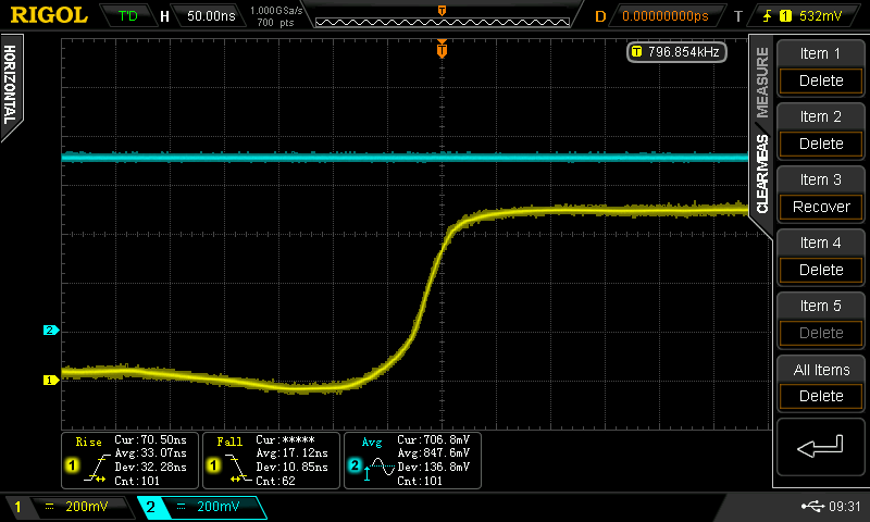
808 mV
By 808 mV, the speed has really picked up: f = 3.7 MHz, tpd = 27 ns, trise = 11.5 ns, tfall = 15.5ns. I forgot to measure the current.
Note that those peaks on the top and bottom are above V+ and below ground - I forgot to move channel 2's reference to match channel 1.
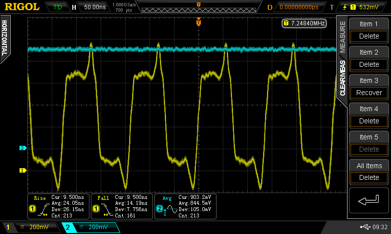
903 mV
The speed has doubled now. f = 7.2 MHz, tpd = 14 ns, trise = 9.5 ns, tfall = 9.5ns, current = 4 mA / gate
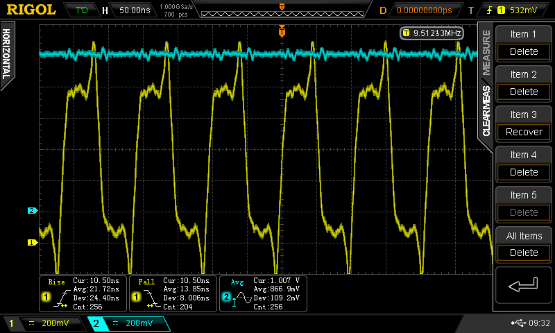
1.007 V
A more modest speed increase. f = 9.5 MHz, tpd = 10.5 ns, trise = 10.5 ns, tfall = 10.5 ns, current = 8 mA / gate.
I'm not sure I trust the scope's auto-measurement of rise and fall time with these waveforms. Next time I'm in the lab, I'll turn on the cursors and see exactly what it's measuring - although 1/5 of a division is 10 ns, which looks about right.
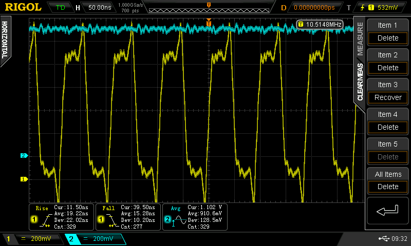
1.102 V
A little more speed. f = 10.51 MHz, tpd = 9.5 ns, trise and tfall about 10ns (scope auto-measurement screwed up), current = 12 mA / gate. This is probably the best voltage to run at.
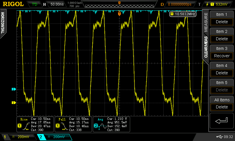
1.210 V
Not much speed increase, just consuming more power. f = 10.58 MHz, tpd = 9.5 ns, trise = 10.5ns, tfall = 10.5ns, current = 18 mA / gate.
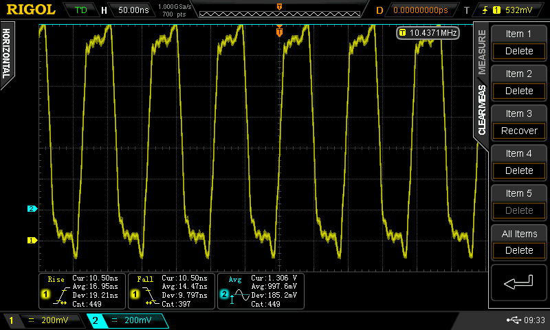
1.306 V
Speed reduced slightly, still more power consumption. 24 mA / gate now.
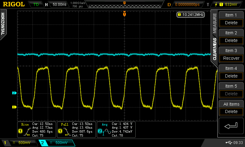
1.404 V
Less speed, more power - 30 mA / gate. The waveforms look superficially nicer, but at the cost of more than 3x the power used at 1.1V and a little less speed.
Summary
It looks like these inverters, with 1k base resistors and 1nF speedup caps, work best at around 1.1V supply. At this voltage, they show a propagation delay of about 9.5 ns. A look at the 74HC04 datasheet shows a typical 9ns tpd at 4.5V supply, which drops to 7ns at 5V supply. Amazingly, it would appear that this simple inverter is almost equivalent to 74HC logic in terms of speed. It doesn't seem like it should be...
When I get a chance, I'll wire a 5/6 of a 74HC04 into a similar ring, and see what that looks like.
Discussions
Become a Hackaday.io Member
Create an account to leave a comment. Already have an account? Log In.
From http://www.diyaudio.com/forums/power-supplies/260132-switching-transistor-off.html :
"Seymour Cray used the PN2369A in the CDC-6600 supercomputer; yes, they
really did build an entire computer out of discrete transistors (!).
It's a gold doped, super high speed switching transistor, meant to be
operated in the saturation region with (Ic/Ib) = 10. But CDC's
computers didn't use TO-92 (plastic) packages; oh no. They use TO-18
hermetically sealed metal packages, and those parts were 2N2369As, not PN2369As."
I happen to have found 50 of these in my "misc. parts box" so the above hints are very interesting ! however, there is no complementary part :-(
Are you sure? yes | no
From the same Mark at http://www.diyaudio.com/forums/power-supplies/260132-switching-transistor-off-3.html:
"I looked up the digital circuit family used to build the CDC 6600
supercomputer in 1964; they called it "DCTL" (direct coupled transistor
logic) and built it out of 2N2369A discrete NPN transistors. Here is the textbook, http://www.textfiles.com/bitsavers/pdf/cdc/6x00/books/DesignOfAComputer_CDC6600.pdf see Figures 12-15 (p.22-24) {warning: large .pdf!}. As you can see, they claimed that DCTL gates have an average switching time of 5 nanoseconds.
I built a 5 stage ring oscillator out of DCTL gates and simulated it in
LTSPICE, schematic attached. The simulated oscillation frequency was
19.7 MHz (using the 2N2369 .MODEL provided by Linear Technology). Thus a
complete period of oscillation requires 50.8 nanoseconds. There are
five transistor switch-on events, and five transistor switch-off events,
in each 50.8 nsec period. They're switching on and off pretty doggone
fast.
The oscillation period of a 5 stage ring oscillator is 10 gate delays (5
gate delays for the high-time, and 5 gate delays for the low-time). So
the average gate delay in simulation was (50.8 nsec / 10 gates) = 5.08
nsec/gate. Just as the CDC guys designed it, fifty years ago. Hats off to you, gentlemen.
A couple of fun facts: the complete CDC 6600 computer system contained
400,000 NPN transistors (p.20) and its mean time between failures due to
transistor failures alone, was "over 2000 hours". About 3 months if
you're running 24 by 7. Gulp!
"
Ted, the type of transistor matters, it seems :-D Of course, stray capacitances and all kinds of passive parts play a role (SPICE simulations are "ideal") but the "regime" of the transistor is critical...
Reducing the signal swing would be a good thing, with a base voltage between 0.4V and 0.7V (for the NPN side) for example, instead of "hard" 0-Vcc, to reduce charge accumulation.
For this, Baker has used a "split resistor" system where the high side and low side can be independently tuned. A capacitor between the bases also helps.
The pursuit of the ideal transistor circuit is a very long quest...
Are you sure? yes | no
I use SPICE enough not to trust it very much.
The other night I had a 5-stage 2N3904/2N3906 ring oscillating at 64 MHz in LTspice. Even using the 1k / 1 nF combination, my current SPICE simulation runs at 25 MHz, more than twice as fast as I've seen on the breadboard.
Are you sure? yes | no
I used LTSpice enough to not trust the single line library that comes with it. If the design is critical, one should hunt for better models. Not sure if it helps, but I usually use LTSpice NPN3 model instead of picking NPN for the non-demanding stuff.
I have seen my simulations didn't agree with real measurements. In my case, IRF MOSFET model from IRF accurately reproduces real life issues which was absent when using the LTSpice library.
Don't get me started on macro models. :P
Are you sure? yes | no
@K.C. Lee I pull in "better" models when I can. I usually find the models for more modern parts are better. Jellybeans use the same model somebody estimated in the 1970s.
Are you sure? yes | no
I know the 2N2369A - I also have a stash of them. It's the classic part to use in the sub-nanosecond avalanche pulse generator from that Jim Williams' app note that re-appears every few years. I never knew what it was originally for :-)
Are you sure? yes | no
I only connected the dots today, even though I'm a long-time CDC6600 fanboy :-D
I must make myself an avalanche generator !
Are you sure? yes | no
@Yann Guidon / YGDES Yes, with a 1 GHz scope, how else are you going to measure the rise time? or evaluate probes??
Are you sure? yes | no
That's my concern these days...
I'm disappointed by the 11302A, considering getting a 2467B : a bit slower, but lighter and can reach 500ps/div (I'm stuck to 5ns/div on the 500MHz-capable 11302 :-( )
Are you sure? yes | no
@Ted Yapo : RTFDS :-D
According to the Book of ONSemi ( https://cdn.sparkfun.com/assets/learn_tutorials/4/2/3/2N3906.PDF ) you can't hardly go faster. The typical fall time (fig.6, p4) is rated at about 15ns for the 2N3906 so you're already "virtually" faster than that.
Going faster requires better/faster parts but this gives us a good estimate of the possible performance for "dumb" parts !
I should try with BFR96 and BFG425 :-D
Are you sure? yes | no
I suspect the 2N3904 turns on before the 2N3906 turns off - creating large shoot-through current spikes, but pulling the output down quickly. Many bypass caps required :-)
Are you sure? yes | no
yes, bypass are critical (like with CMOS).
You could measure the shoot-through spikes with a 1 or 10 ohms resistor in series with the collectors.
This makes me think again of the "diamond" topology, which could reduce this kind of problem... I've seen it on the web a couple of days ago and can't find yet the page, sorry, but some search-fu would help you.
Are you sure? yes | no
TODO : split the base signals and feed them with indepedent RC networks.
Then check if this is faster...
(the Baker circuit has such a split drive, I suspect there is a good reason)
Are you sure? yes | no
My suspicion is that this allows a higher and less sensitive supply voltage, not that it's there for speed reasons. But, it's something to try.
Are you sure? yes | no
It could help, I think, because each transistor will require the extra "kick" at different times (due to Miller effect occuring at different levels), yet they have to share the single drive...
Another thing to consider : 1nF (shared between two bases) is different from 2×1nF, that's more drive for each base.
Are you sure? yes | no
AMAZING
it's as fast as HC, but does it consume as much at this frequency ?
Since the voltage is 4× lower, then power efficiency might be "interesting", which could justify its use for the #YGREC-Si ...
Now it's important to make a MUX2 or MUX4 !
Are you sure? yes | no
Maybe I didn't do the math right. I have it in my head to divide the oscillation period by 10 to estimate the prop. delay. But some voice is whispering "five". Now I either have to find a reliable reference or convince myself on paper. Unless you have a convincing argument :-)
Well, muxes aren't as easy here as in CMOS, because you can't make transmission gates. You have to make logic muxes, which are slower. But, if you can make a NAND, you can make a MUX.
Power would seem to be 13 mW / gate at 10 MHz for these inverters as used. Power for the 74HC04 is:
Pd = (Cpd + Cl) * Vcc^2 * f for driving a load of Cl
this is 6.1 mW/gate at 5V, 10 MHz, using the datasheet figures. Half as much,
Are you sure? yes | no
OK it's not as good as HC but compared to LS or F, pretty good !
It's very tempting... But I need good MUX gates...
Are you sure? yes | no
BJT-based transmission gates is an interesting subject for me...
Hey this gives me an idea
Are you sure? yes | no
I got the math right.
https://en.wikipedia.org/wiki/Ring_oscillator
Are you sure? yes | no
So, what speed do discrete transistor logic designs usually achieve?
Are you sure? yes | no
it depends on many things...
I still have to evaluate and test with ECL / "current steering logic", non-saturated circuits...
Here the circuit saturates pretty hard... I would try to keep the electrical levels in the linear region...
Are you sure? yes | no