 Ted Yapo
UPDATE: the speeds measured here don't represent the true switching speed of these gates. See this log for more details.
I initially settled on 1 nF speedup capacitors because they seemed to perform better in simulations - which were done with lower-frequency signals. The value did seem large at the time, but it seemed to work OK in practice, even though the ring-counter simulation would go much faster with smaller capacitors. I finally got around to trying smaller capacitors on the real hardware. With 100pF caps substituted for the old 1 nF's, everything goes more than twice as fast (with a catch, discussed below). The ring counter went from around 10 to 25 MHz:
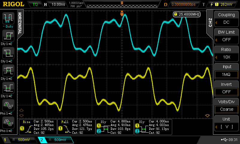
This frequency implies an average propagation delay of 3.92 ns. The scope measures 4.0 and 4.9, but may be confused by the under/overshoot. In any case, it's more than twice as fast as the previous circuit which had around 9.5ns of average propagation delay. A 74AC04 inverter has a typical propagation delay of 3.5 (TPHL) or 4.0 (TPLH) ns. This silly CBJT logic has gone from 74HC speeds to 74AC. Or so it would seem.
What's the catch?
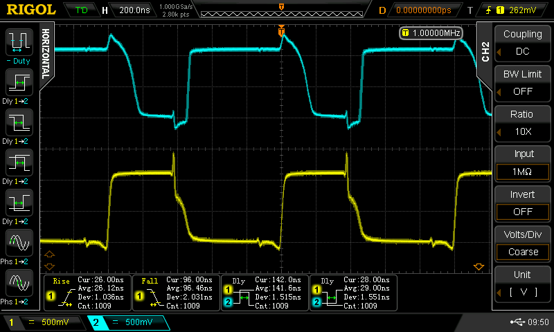
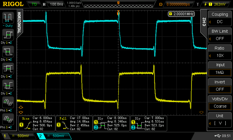
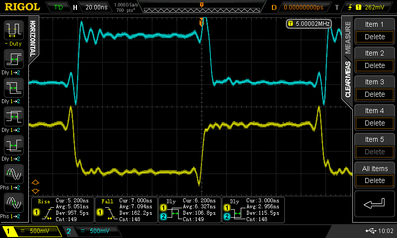
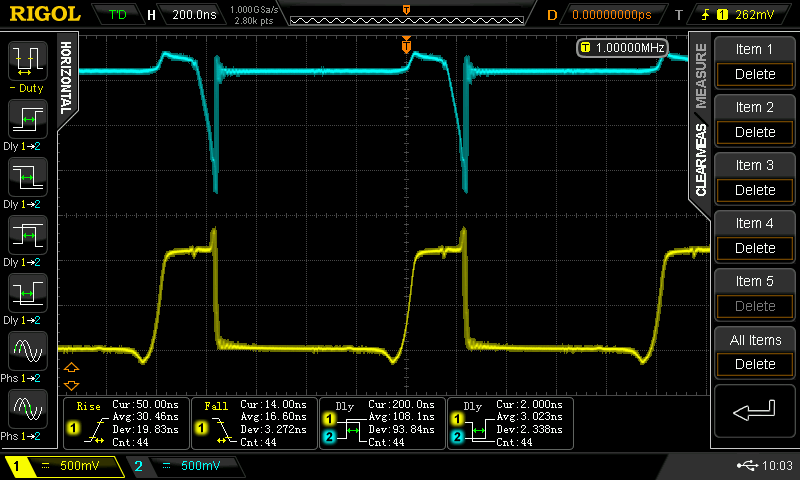
Knowing my luck, there has to be a problem somewhere. It didn't take long to find it, either. At lower speeds (when driven with the signal generator), the waveforms fall apart - I saw this behavior in the simulations, too, which made me think larger caps were necessary. For example, a chain of inverters driven with a 1 MHz squarewave looks terrible (below, left). The same inverters look fine with a 2 MHz input (below, center), and OK to the top of my generator at 25 MHz (10 MHz shown below right) - some of that ringing is the ground leads on the probes; I was too lazy to solder on Z0-probes.
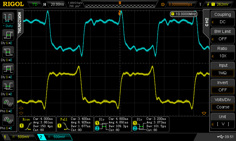
100 pF just isn't enough at lower frequencies, which is bizarre, because it should be all about edges. Did I screw up and have the DDS set for a sine wave output?? Is the DDS edge rate lower for lower frequencies? Now I'm going to have to re-check when I get a chance - maybe this is something simple. It would be convenient if this bizarre behavior at low frequencies just went away :-)
And the NAND?
The NAND gate performance was also improved with the smaller capacitors - at least for higher frequencies. Driving the lower input showed a 3.3 ns TPLH and a 6.3 ns TPHL (the 74AC00 has 6.0 and 4.5 ns at 5.0V, respectively):
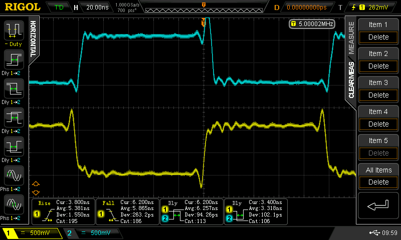
With the upper input driven the NAND shows a 3.0 ns TPLH and a 6.3 ns TPHL - the input speeds are now basically symmetrical unlike with the 1 nF speedup caps. This is good.
Oh, and if you drop the input frequency to 1 MHz or below, everything falls apart again. At DC, things work fine, as expected. I didn't measure the range of frequencies for which it's screwed up. I think this needs more bench time.
It's another mystery!
Discussions
Become a Hackaday.io Member
Create an account to leave a comment. Already have an account? Log In.
FYI: LTspice: Using the .STEP Command to Perform Repeated Analysis
http://www.linear.com/solutions/1831
Are you sure? yes | no
yes, I've noticed you're another LTspice fan. I've long used the .step command for parameter and temperature sweeps - very handy. Just the thing for finding an ideal capacitor value - if that was the only problem :-)
I recently learned that you can step an entire model - like iterate over a list of MOSFETs, for example:
http://ltwiki.org/index.php5?title=Undocumented_LTspice#Stepping_a_Model
I found this really useful, too.
Are you sure? yes | no
Oh my, the CBJT system is getting even more interesting !!!!!
Are you sure? yes | no
Interesting, indeed!
Are you sure? yes | no