 Justin Maynard
The eureka part of this project is putting the WS2812 LED’s behind the 2x2 button pad.
The idea for the project came when testing out my reflow oven with a Sparkfun Simon Says kit.
I realised the button pad would be a great user interface for controlling things and paired up with the the wifi devboard the (at the time) soon to be released SparkCore would be ideal. Then I was looking that the Simon Says and realised the SparkCore didn’t have enough pins to for 4 RGB lead’s and that’s when i discovered the WS2812 RGB LED’s.
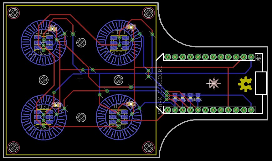
Prototype version 1 had the button resistors on the back of the board, necessitating reflow of both sides. As i’d like to do a small batch of these at some point I redesigned the board bringing the button resistors to the front of the board.
There are pads on the back for the WS2812 power resistors but I’ve found that they are not really necessary the LED’s power is more of a star configuration than a chain and its’ only 4 LED’s
The other change from version 0.1 to 0.2 was learning to tent my vias to reduce the chances of a short near the button pad.
The reason for the shape of the current protypes is simply that there was large sections of unused board and i’d never made a non rectangular board before so it was more just testing out shapes than anything else. The next version of the board is going to go back to rectangular it’s easier to mount in a case and the spare area will be populated with space for optional extra sensors.
Discussions
Become a Hackaday.io Member
Create an account to leave a comment. Already have an account? Log In.