 agp.cooper
The Forward Channel
I have simulated many options but I have not really done much better than the current setup. The backward channel without any additional filtering is suppressed nearly 20 dB. Really I have to wait until I physically test the modem with the presence of the backward channel before spending too much more time.
The Backward Channel
The backward channel is 387 Hz (space) and 487 Hz (mark). If I lowpass the signal (e.g. 585 Hz) and then down sample to 3300 Hz (from 13200 Hz) then the existing modem code will work fine for backward channel. The main problem is that the 2200 Hz frequency is aliased as 500 Hz. So I will need a good lowpass filter before the down sampling.
More thought is required.
Filter Madness
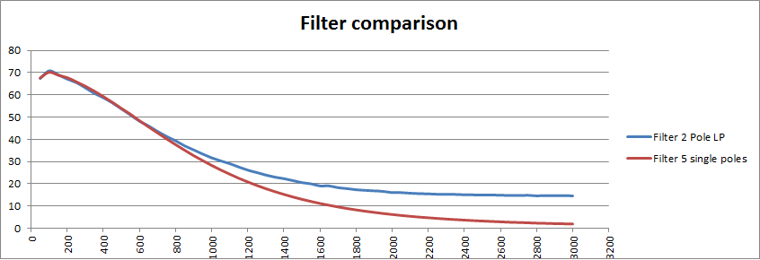
Spent a lot of time playing with filter parameters to avoid proper division (can only use arithmetic shift right). Looking at cascading single pole filters. Easier to design, numerically efficient and works more or less the same. Here is a 5 single pole versus the current two pole lowpass:
Code for the 558 Hz 2 pole lowpass:
- LP0=(S0+S1+S1+S2+41*LP1-13*LP2)>>5;
- About 7 us.
And for the 5 single pole version:
- A0=(S0+A1)>>1;
- B0=(A0+B1)>>1;
- C0=(B0+C1)>>1;
- D0=(C0+D1)>>1;
- E0=(D0+E1)>>1;
- About 6 us.
So the five single poles works better and is faster!
Modem Output
If I want to configure the modem for both forward and backward output then I will need to review the output filter. One option is to increase the number of steps for the DAC for the backward channel.
More thought is required.
More Code
Rewrote the code so the the modem can be send mode or answer mode. I have not tested it yet but I need to consider the digital to analog conversion (DAC) and the output lowpass filter. The question is do I really need to try so hard to filter out the DAC quantization. Here is the what I am thinking:
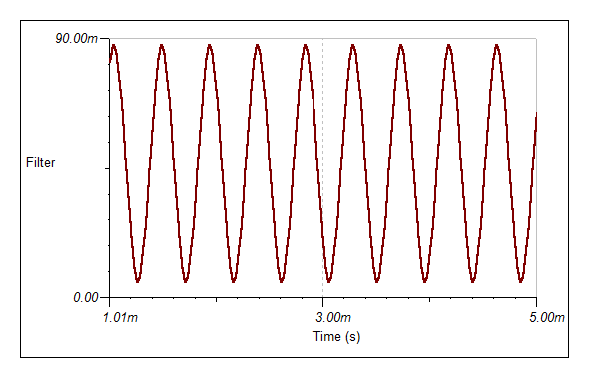
At 2 bit 2200 Hz is fine:
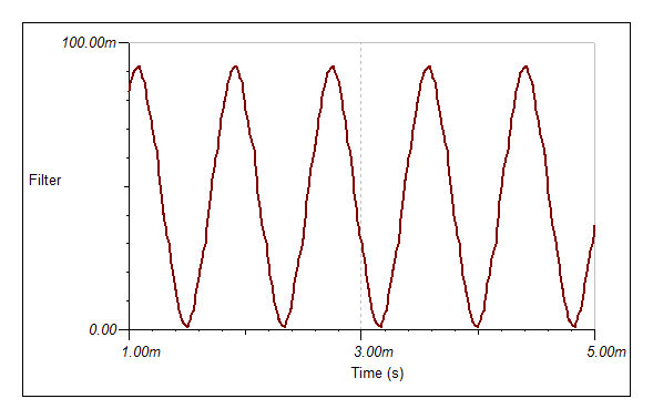
And at 1200 Hz the wave form is still okay:
But at 387 Hz:
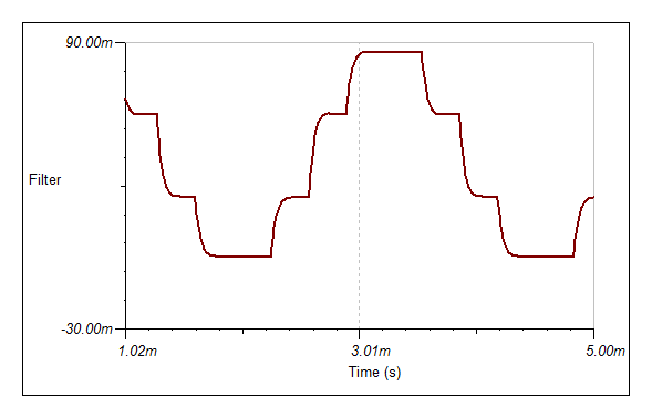
This will probably not work will (but I have not tried).
But if I use three bit, the wave form is greatly improved:
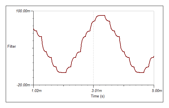
So perhaps 4 bit is the way to go. The advantage of the above circuit is that the amplitude does not vary very much and the power level is probably about right (125 uW) but can be increased in necessary.
Four Bit Version
Here is a four bit version showing 387 Hz and 2200 Hz:
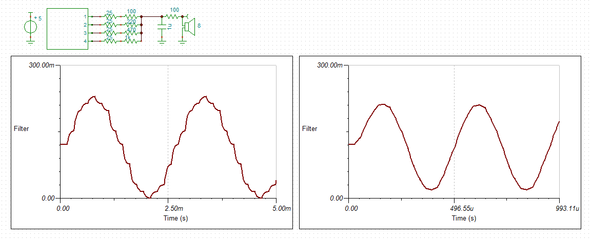
With the four bit version the resistor ladder network does not have to compensate for the lack of bits. The 25 R resistors are the uP source impedance. The power level is about 0.1 mW which will probably need to be scaled back.
PWM Check
Just to double check, I reconsidered PWM. First the ripple was about the same for the same RC values using a PWM frequency of 31.25 kHz for only the 387 Hz case. However, ripple frequency for the PWM much higher will present as a 4850 Hz alias for the answer modem (i.e. 2200/1200 Hz) and a 1750 Hz alias for the send modem (i.e. 487/387 Hz) so will not present a problem (if any gets through the phone line filters). For the answer modem the sensitivity to the 4850 Hz signal is attenuated about 20 dB (the attenuation is similar for the send modem). So the PWM option will work as well.
Now at this time you may be wondering why I did not go with PWM in the first place? Well basically I could not model the PWM frequency affect on the modem response then!
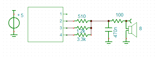
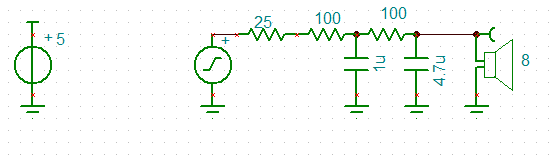
I like simple so back to PWM:
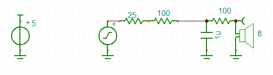
The PWM filter works for low frequencies but the ISR generates a square wave for 2.2kHz. Pretty ugly. Added another capacitor across the speaker to clean it up. Looks more like a triangle wave but good enough. Here is the PWM circuit:
AM Demodulator
I had a play with the decoder and reworked it as an AM demodulator:
If I wanted to create my own protocol I could mix binary FSK with binary ASK!
Bell 103A Work
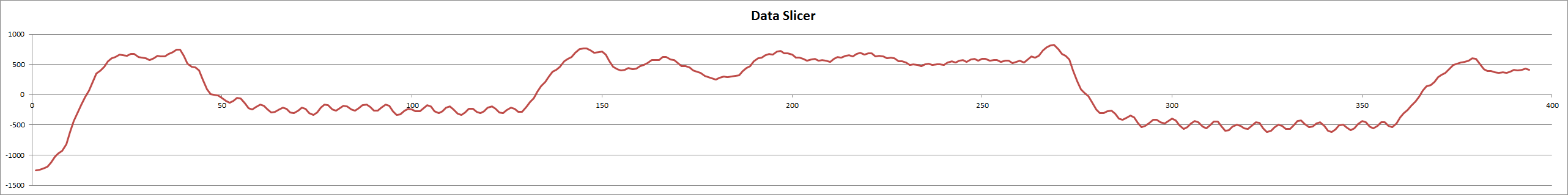
The first observation is that there are a number of configurations that need to be tested and it is rather a headache! First is to determine suitable sampling rates for the originate and answer decoders. Integer multiplies work best and the sample rates determined were: 22 kHz (2200/2000 Hz) and 12 kHz (1200/1000 Hz). The Biquad LP (330/140 Hz) was unstable so a two stage low Q (0.5 each stage) state variable low pass filer was used. For the band pass (2200/1100 Hz) I used a medium Q (5.5) biquad. It works but transit ripple causes problems. Further work is required. Here is the frequency response for a delay of 8 for both originate (22k) receive (2200/2000 Hz) and answer (12k) receive (1200/1000 Hz) modem decoders:
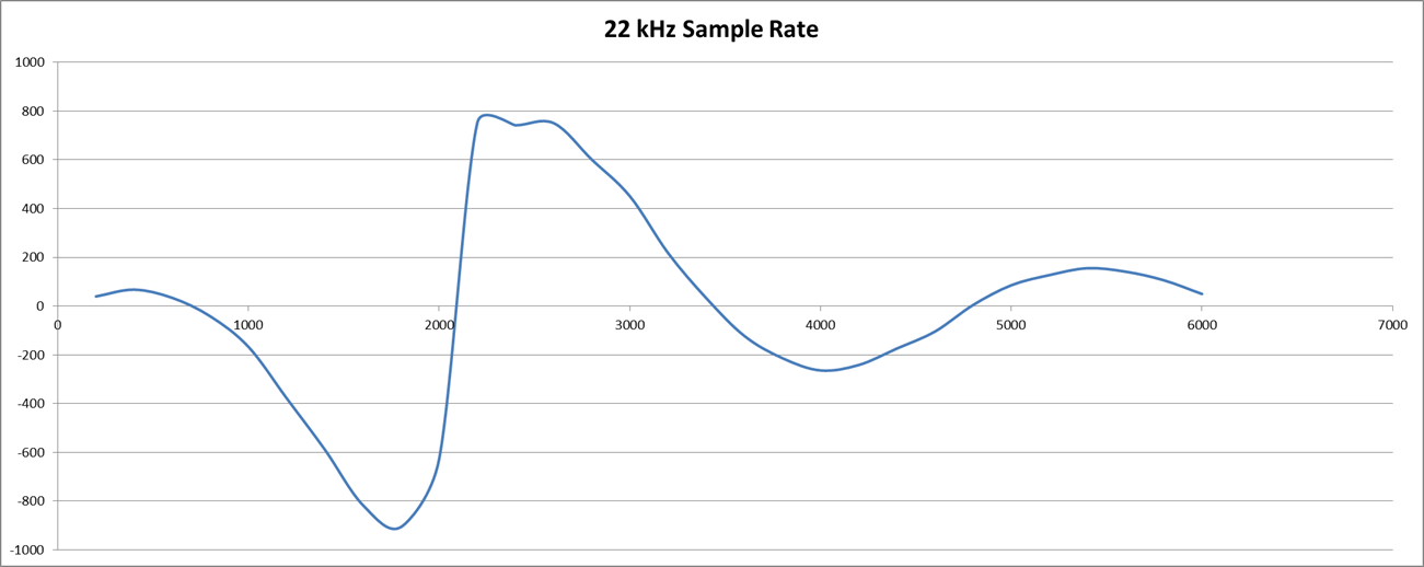
 Pretty nice as only the sample rate was changed.
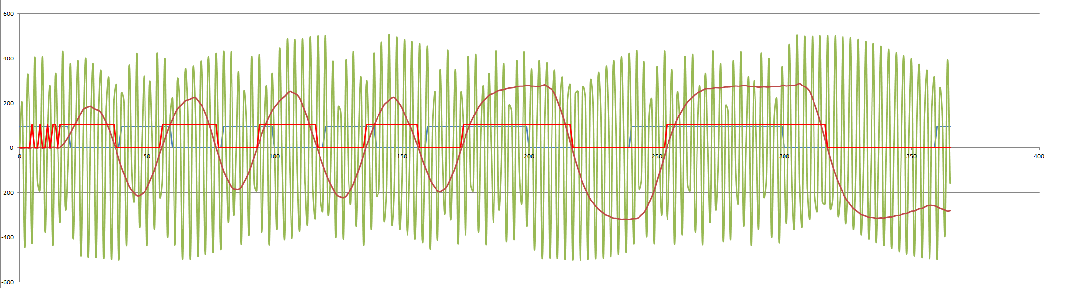
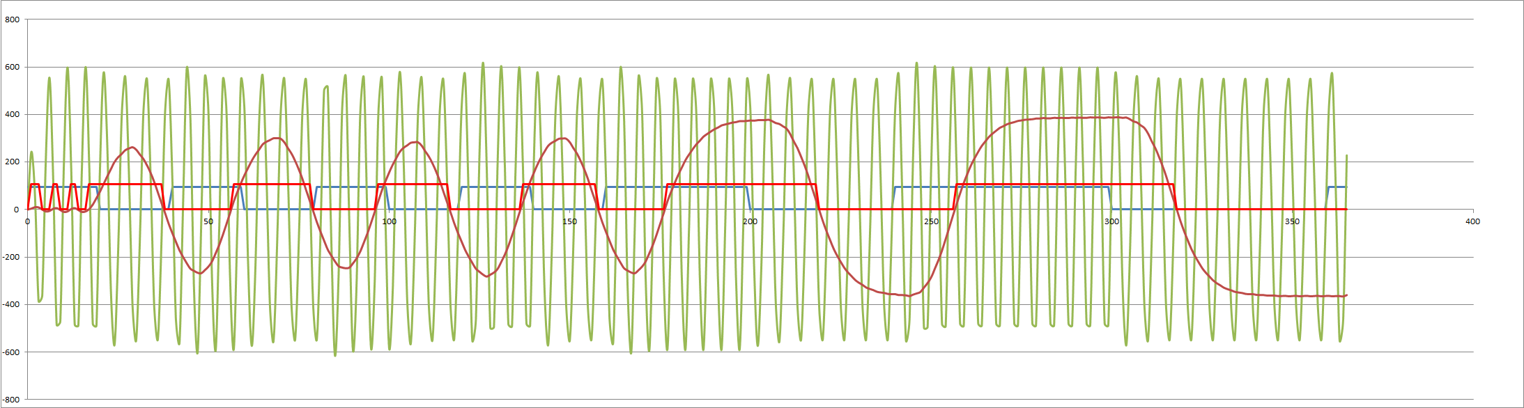
But I get some decoder issues (probably phase (beat) issues) (note the variance in the first three positive peaks):
 If I change the sample frequency to 13200 Hz (from 12000 Hz) and delay to 9 (from 8), the issue disappears?
 I am going to have to understand/model the demodulator function more directly.
The other issue I ran into was that the transmit frequencies are difficult to generate from the receive sample clock (Timer0) so I need to look at using either the PWM timer (Timer2) or Timer1 to handle the transmit frequencies.
So there is still a lot of work getting everything working together in the best possible way.
Mathematical Help
Trial and error is expensive so I spent the afternoon doing the decoder maths. Not hard, end up with:
- Correlation = 1/2*Cos(-2*Pi*f*d), where 'f' is the frequency and 'd' is the delay.
As I am interested when the correlation crosses the axis (i.e. the centre frequency) the function simplifies to:
- d = (2*n+1)/4*Fsample/Fcentre, where 'n' is a positive integer.
Note I am restricting myself to integers (non-integers will work but are not optimal).
For n=0 I get d=3 (assuming 13200 Hz sample rate) and the response looks like this:
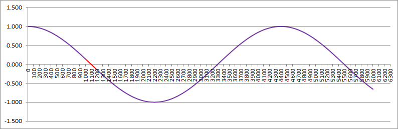
The red is the range of interest (note the correlation is negative).
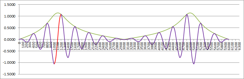
For n=1 or d=9 (what I was using) the response is:

Better but the decoder has a better response to other frequencies that are not of interest. Thus the need for a bandpass filter. Without a bandpass fllter the optimal response is n=5 or d=33:

At least here no other frequency is better.
By inspection you can work out that the optimal delay is:
- d = Fsample/2/(Fmark-Fspace)
Optimal Sample Rate
The next problem is what is the optimal sample rate. Tough! From the above maths I can only say it is a multiply of 400 Hz (= 2*(Fmark-Fspace). I know I get a good result at 13200 Hz and 12000 Hz but can I go lower?
It has to be greater than 2 x Fmark (2400 Hz). If we use this number then the correlation depends on the signal to sample phase. Not good. I can now say it has to be at least 3 x Fmark to avoid really bad "beating".
I ran a few simulations until I realised that the signal generator was not working correctly. Now that it is fixed, the decision on the sample rate is really based on the bandwidth of the telephone system (i.e. from 300 Hz to about 3400 Hz). Therefore the minimum sample rate should be about 6000 Hz. Here is the calculated sensitivity (combined modem and bandpass filter) for a 6000 Hz sample rate:
Note the alias on the right beyond 3000 Hz.
Updated Modem Code
Here are the updated modem results.
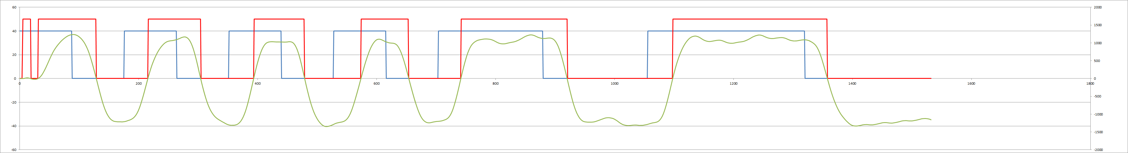
The originate 1000/1200 Hz:
 And the answer 1200/2200 Hz:
Recalibration
As I seem to have the modem decoders working properly, it is about time I adjusted the frequencies to match the specifications:
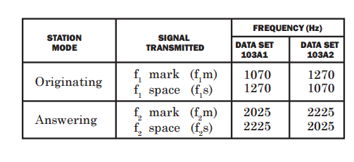
Note I am working with the Bell 103A2 set.
AlanX
Discussions
Become a Hackaday.io Member
Create an account to leave a comment. Already have an account? Log In.