 agp.cooper
Loopback Test
I had some problems with the audio loopback so I had to drop back to a direct loopback.
Here is the signal from the first stage lowpass:
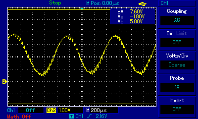
Not pretty but functional. Some noise is probably a good idea for testing and optimising.
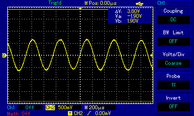
Here is the demodulator output:

Basically identical results for Answer or Originate configuration. What is not shown here is the decoder jitter.
Baud Rate Generator
The jitter associated with the baud rate generator was the main problem. It was missing the timeout flag. Fixed. It now only misses the occasion interrupt tick from the sample clock.
Demodulator Jitter
The jitter associated with demodulator is likely to be jitter from the sine wave generator and/or from the phase transition. Suppressing the high frequency noise by adding an additional low pass had no effect:
The only real hint is that jitter is much worse (x4?) with the higher frequencies suggesting jitter is from the sine wave generator.
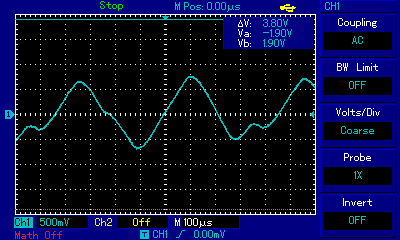
Turned off the binary signal (i.e. a single tone) and the jitter is clearly visible and in tune with the demodulator jitter. Here is the signal, even in this image you can see this signal moves around:
Bandpass Filters
Before I found the baud rate generator problem I reduced the band pass filter Q to good effect. After minimising the remaining jitter I will have to rework the band pass filters to see if I can increase the Q as I think suppressing the opposite channel still has merit.
Sine Wave Generator Investigations
Tried a 62.5kHz Fast PWM, 32 bit maths and a 256 sine wave lookup table (and variations in between). The sine wave looks great but slowly oscillates. The demodulator hates it! After double checking I find the frequency is off which means the Arduino cannot keep up (even with just the sine wave generator running). Back to 31.37 kHz.
Now I was caught out in that I thought the Phase Correct PWM frequency is half of the Fast PWM frequency of 62500 Hz. It is not! It is actually 31372.5 Hz. It pays to check the manual.
I have come to the conclusion that the jitter is mostly due to background interrupts by the Arduino bootloader. This probably means that I am losing interrupt ticks. I did drop the PWM to 7813 Hz to have a look, but the wave form was pretty poor:
Data In Versus Data Out
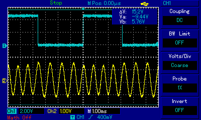
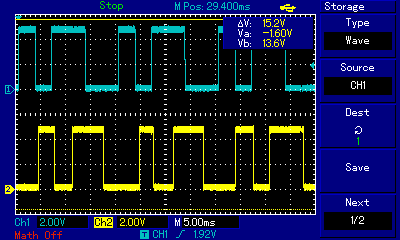
Here is the Data In (blue) versus Data Out (yellow). Note that Data Out is delayed by about a bit:
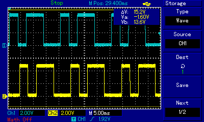
You might say what jitter? That was the low channel (1170 Hz), the high channel (2125 Hz) is not so good:
In reality the background jitter is just like a noise floor. It just sets a minimum for degradation by the telephone system. I could spend weeks investigating jitter and trying solutions but I feel I have a fair solution right now so I will move on.
Audio Loopback
Now that I think I have the code working properly, here is the results of the audio (speaker and microphone) loopback for the low channel:
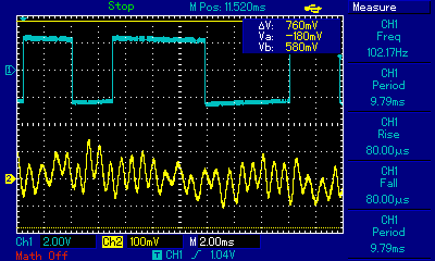
The signal looks to be all over the place but it detects okay with the usual jitter.
Here is the high channel:
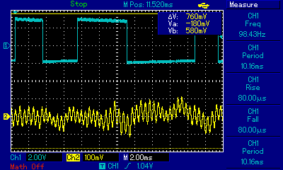
Detection is good with the speaker to about 30 cm away. Without the speaker connected you get the usual spike chatter.
The microphone gain is far too high, someone talking in the room is stronger than the signal. But the next circuit board iteration has that fixed.
---
So lots of progress today! A working modem!
Alanx
Discussions
Become a Hackaday.io Member
Create an account to leave a comment. Already have an account? Log In.
If your cell phone is using the AMR codec, the pitch is only updated at 5ms intervals. None of the other speech codecs used by cellphones offer any finer temporal resolution. Sending 300bps (3.33ms per bit) might be a problem.
Are you sure? yes | no