 agp.cooper
Modem Version 2
Here it is:
Testing the Output
Here is a 1200Hz output at the DAC:
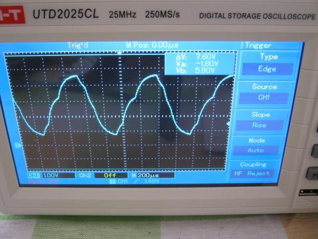
An after the low pass filter:
The designed peak to peak voltage is 3v. The output is offset to maximise the emitter follower voltage swing.
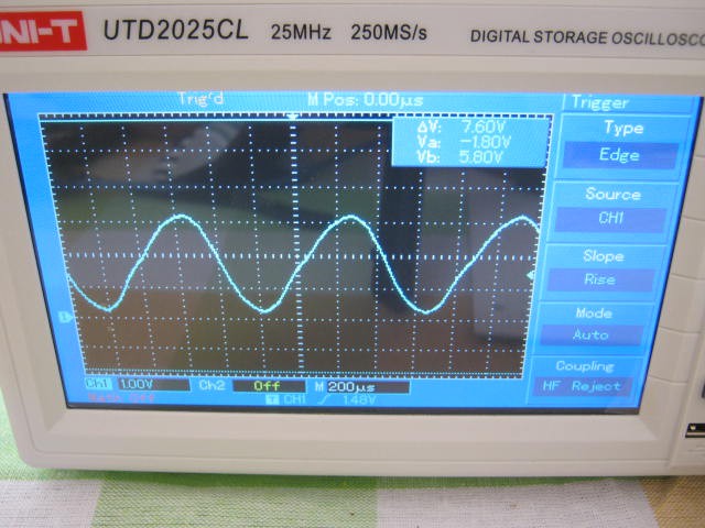
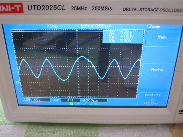
Same again for 2200Hz:

And after the low pass filter:
The designed peak to peak voltage is 2v.
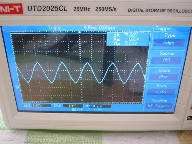
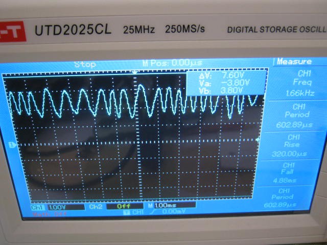
Here is a binary signal after the low pass filter:
Here is a random signal after the low pass filter:

On the Receiving Side
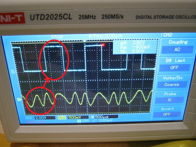
The modem did pick up and demodulate a 500 uW audio signal from the speaker at about 1 cm away from the microphone but the microphone and transistor amplifier are rather non-linear with 1 to 2 volt voltage swings and is demodulating the amplitude modulation on the input signal:
 Note that the top of the signal has less range than the bottom of the signal.
Demodulation Updates
Had some problems demodulating the audio signal. Found some coding errors introduced in the last code update. Fixed. I also reworked the high pass to more aggressively remove the DC bias and to undo the low pass mark/space amplitude differences.
Here is the audio signal (~0.7 vpp) after the pre-amp and the demodulated signal (note that the demodulated signal is delayed by about 1 bit:
Have to be happy about this!
More work is required because demodulation fails at less than 0.5 vpp. With about 500 uW of speaker power and the speaker about 1 cm away from the microphone, the audio signal amplitude post the pre-amp is about 1 vpp (about where I want it).
Perhaps I need to consider some automatic gain control (AGC)?
Fine Tuning the Code
Debugging interrupt service routines (ISR) on an Arduino is hard work. You cannot just print debug information from inside the ISR. There are ways around this.
Anyway, I exported the variable data, line by line, checking and correcting. Had to relearn operator precedence order, and changed the DC bias code to something I found on the Internet (thanks: sam-koblenski.blogspot.com.au/2015/11/everyday-dsp-for-programmers-dc-and.html). Added another DC bias adjustment to the correlation output. It works very well now, down to just above the noise level (i.e. the fan of my oscilloscope delivers 100 mV pp post the pre-amplifier). Here is the demodulator code:
// Decode the data
X1=X0;
Y6=Y5;Y5=Y4;Y4=Y3;Y3=Y2;Y2=Y1;Y1=Y0;
Z2=Z1;Z1=Z0;
F2=F1;F1=F0;
G1=G0;
Sx=analogRead(A0)-512; // 18 us
X0=Sx+(3*X1>>2);Y0=X0-X1; // Remove DC offset
Z0=(Y6>=0)?Y0:-Y0; // Switching mixer
F0=(Z0+Z1+Z1+Z2+F1*40-F2*12)>>5; // 600 Hz low pass filter (8 us)
G0=F0+(3*G1>>2);H=G0-G1; // Remove DC offset
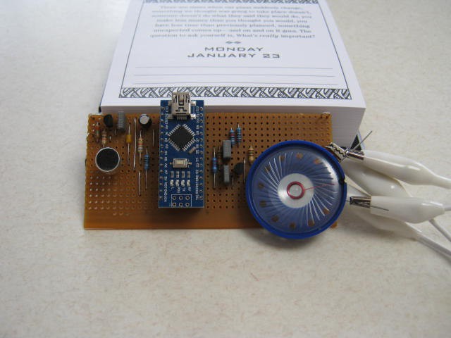
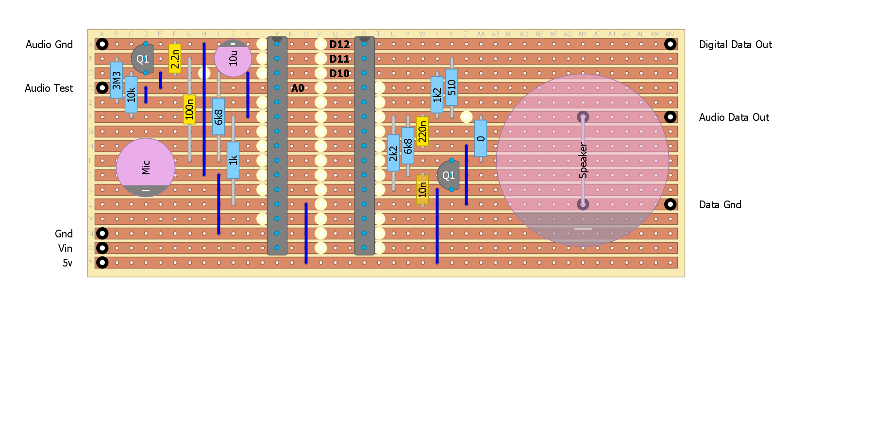
DataIn=(H>0)?1:0; // Test correlationNote: all variables are 16 bit integer.I don't think I need any more sensitivity but if I did, then filtering off of the high frequency noise would help (i.e. the demodulator is sensitive to any frequency above 1700 Hz as the mark frequency). I could roll off the microphone a little faster by adding a 2.2uF across the microphone pins. Actually, that did not work, it made it worse - parasitic oscillation? Here is the current strip-board layout:
TBC...
AlanX
Discussions
Become a Hackaday.io Member
Create an account to leave a comment. Already have an account? Log In.