 Dan Julio
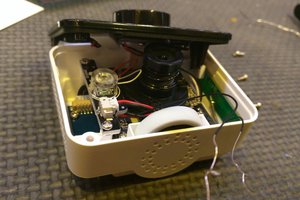
The drone is comprised of the plastic body powered by a 2-cell LiPo battery (charged from a 5V input) and servo directed camera sitting underneath. The servo is a 5-wire connection (probably 2-motor, 3-pot). The camera connects via a 4-wire 3.5mm audio-jack connector and has an external WiFi antenna. The remote control is a basic unit communicating via a 2.4 GHz signal (probably something like an NRF24L01+ clone - yet to be determined). It can control the drone with traditional controls such as roll, pitch, yaw and throttle. It also provides the ability to take pictures (and store them to a micro-SD card) or start a video recording as well as initiate take-off, landing or perform a flip. The "Promark VR" app connects to the drone (camera) via WiFi and can also control flight as well as take pictures and video stored on the phone. The drone acts as the WiFi AP and the app connects to it. Of course I immediately figured there was a small Linux computer in there somewhere.
It flies reasonably well, although without any sophisticated features found on more expensive devices. They claim 300m for the remote and 100m via WiFi. Video is decent resolution but not accurate colors. They don't document the micro-SD card in the back of the camera but it will store both snapshots and video on the card if one is present.
I accidently put some run-down batteries in the transmitter and during a flight the transmitter turned off while the drone was moving quickly away. By the time I figured out the problem and was able to turn the transmitter back on, relink it to the drone and send a "land" command the drone was pretty high up and came down hard. It sheared off two landing struts and banged up the camera pretty bad. That seemed a good reason to take it apart and see how it all worked. Following are notes as I look at the various subsystems in this toy.
Some online research hints that this drone may be related, at least technology-wise, to the Syma X8WC.
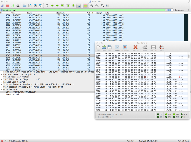
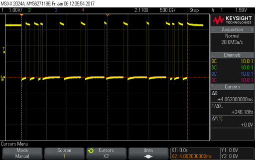
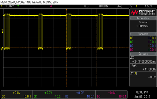 The smallest "bit" period in the frame is about 52 uSec which implies a bit rate of 19,200 baud and an 8-byte packet. Sure enough connecting the signal to the USB serial converter and a 19.2 kBaud 8N1 terminal connection yielded what looked like good data. Even better data seemed to be byte aligned and I saw direct changes when I manipulated the on-screen controls. What follows are the notes I took while associating data with control action. At the end is my guess as to what each byte means. The trim controls simply seem to add a small + or - offset to the actual control value. The start-byte and end-byte sum to 0xFF and the remaining bytes are protected by a XOR checksum.


 ril3y
ril3y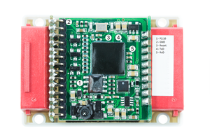
 seasonalvegetables3
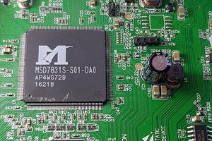
 Enki
Enki
Hey I am also trying to hack a WiFi Drone too, feel free to look over my info too and if you had any comments I would love to hear them.
I believe we have the same microcontroller chip
https://hackaday.io/project/181753-obtaining-control-of-jxd523-the-20-drone