 Dan Julio
I guessed that the phone app opened some sort of socket communication channel with the "aircraft-ctl" program running on the camera board. I figured the thing to do was to try to capture the packet stream between the camera and app and then find out the packets associated with the controls. I started with Wireshark running on my Mac with the Mac connected to the camera's WiFi network. Even though I had selected promiscuous mode, I got nothing of interest initially. I figured the Mac's WiFi interface couldn't see packets that weren't related to it's traffic. So I went looking for apps to run on the phone itself and found tPacketCapture. It looked promising and I did some experiments with it. It acts as a proxy to capture all network traffic in and out of the phone and generates a pcap file that can be viewed by Wireshark. Unfortunately it slowed down network traffic (not entirely sure why - perhaps my phone is too slow) and I ended up losing a lot of packets and couldn't really make heads or tails of the data except to suspect that the app was sending UDP packets with the control information to port 8080 on the camera (my earlier prediction of a TCP telnet-like service was wrong). But UDP made sense since the app might just stream the packets like many simple remote controls and the loss of a few packets here or there wouldn't matter (just like a traditional RF remote control). Back to the drawing board (google...) and I was able to ascertain that the WiFi interface on my Mac did, in-fact, support a monitor mode which could be enabled in Wireshark to see all WiFi traffic. I enabled it and success! I saw all communication with the camera board. Sorting on UDP packets yielded a constant stream of 11-byte packets to port 8080 whenever the app on-screen controls were enabled. Control packets seem to be sent on approximately 25 mSec intervals and simply represent the state of the controls when they are set (e.g. bits might remain set as long as an on-screen button is pressed).
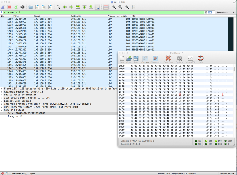
I displayed the serial data from the camera board in a CoolTerm window and then set about methodically capturing the packets as I manipulated only one control at a time. This way I could more easily associate changing data in the UDP packet with the serial data sent from the camera to the drone's controller. I ended up generating 16 different captures (my notes with some raw data analysis at the end of this log entry) and was able to figure out the basic format of the UDP packet.
11 byte UDP packets: (about every 25 mSec)

  Bytes 0:1 = 0xff04 which seem constant

  Byte 2 = Throttle (8-bit values 0x00 - 0xFF).  Directly output in serial stream.

  Byte 3 = Rotate Left/Right (7-bit value 0x00 - 0x7F, center 0x3F).  Remapped around 0x80 on serial.

  Byte 4 = Forward/Backward pitch (7-bit value 0x80 - 0xFF, center 0xC0).  Remapped around 0x80 on serial.

  Byte 5 = Left/Right pitch (7-bit value 0x00 - 0x7F, center 0x3F).  Remapped around 0x80 on serial.

  Byte 6 = Rotate Trim (5- or 6-bit value 0x00 - 0x1F or 0x20, center 0x10).  Added or subtracted from Rotate value.  Bit 7 indicates takeoff/landing controls displayed.

  Byte 7 = Forward/Backward trim (6-bit value 0x20 - 0x00, center 0x10).  Added or subtracted from Forward/Backward pitch.

  Byte 8 = Left/Right trim (6-bit value 0x00 - 0x20, center 0x10).  Added or subtracted from Left/Right pitch.

  Byte 9 = Flags

     Bit 7: Set initially when either takeoff or landing pressed

     Bit 6: Set after bit 7 for takeoff

     Bit 5: Emergency stop (bit 7 is also set)

     Bit 4:

     Bit 3:

     Bit 2: Normal/Headless

     Bit 1:0: Speed Model

       00 : 30%

       01 : 60%

       10 : 100%

       11 : Unused

  Byte 10: Checksum (added to bytes 1-9 = 0xFF)
Questions remain about the header byte values. Is that a fixed value or could different header bytes (especially byte 1 : 0x04 - since it is included in the Checksum) have additional packet information? What, if anything, do the unused bits in the trim bytes and flag byte mean?
Most UDP data was directly mapped (potentially shifted) to the serial data stream. However the Speed Model seems to affect the mapping of control data to serial data, perhaps exponentially. The faster the Speed Model, the faster the serial data changes (less fine control).
Probably a follow-on activity is to write a program on the computer to open a UDP socket connection with the camera board and make sure that I can send bytes to control the output. This might make it easier to figure out what the unknown bits do. Interestingly, at this point, the camera board could be used as a controller for some other project, like a remote-controlled car with video feed, or simply a webcam with servo pan/tilt. Both would require some external controller to take the serial data stream and control the motors or servos but this is something an arduino or other 8-bit micro could easily handle.
Data Format Analysis:

Line 1: Wireshark UDP -> port 8080: ff04003fc03f101010008d

Line 2: Serial Output


—data without header or checksum bytes—
  - Wireshark packet is 8 bytes long
  - Serial packet is 5 bytes long

controls displayed -> takeoff/landing displayed -> takeoff -> takeoff/landing undisplayed -> controls undisplayed

00 3F C0 3F 10 10 10 00

80 80 00 80 00

7E 3F C0 3F 90 10 10 00

80 80 7E 80 40

7E 3F C0 3F 90 10 10 80

80 80 7E 80 42

7E 3F C0 3F 90 10 10 40

80 80 7E 80 41

00 3F C0 3F 10 10 10 00

80 80 00 80 00

controls displayed —> throttle up then down —> controls undisplayed

00 3F C0 3F 10 10 10 00

80 80 00 80 00

00 42 C0 3F 10 10 10 00

00 43 C0 3F 10 10 10 00

00 43 C0 3F 10 10 10 00

00 43 C0 3F 10 10 10 00

00 43 C0 3F 10 10 10 00

04 44 C0 3F 10 10 10 00

0A 43 C0 3F 10 10 10 00

14 43 C0 3F 10 10 10 00

1A 42 C0 3F 10 10 10 00

26 41 C0 3F 10 10 10 00

2C 41 C0 3F 10 10 10 00

38 41 C0 3F 10 10 10 00

3E 41 C0 3F 10 10 10 00

4C 41 C0 3f 10 10 10 00

54 42 C0 3F 10 10 10 00

… up to

F2 45 C0 3F 10 10 10 00

… down to

00 3F C0 3F 10 10 10 00

^

+— Throttle

Serial Output:

80 80 TT 80 00 where TT is throttle with sequence:

  26 2C 38 3E 4C 54 … F2 … 00

controls displayed —> takeoff/land displayed —> rotate left then right then center —> controls undisplayed

00 3F C0 3F 10 10 10 00

80 80 00 80 00

7E 3F C0 3F 90 10 10 00

80 80 7E 80 40

TT RR C0 3F 90 10 10 00

80 80 TT RR 40

  TT = Throttle

  RR = Rotate

(many more UPD packets than serial packets)

RR went essentially between 00 - 7F (7E)

7E 3F C0 3F 90 10 10 00

80 80 7E 80 40

controls displayed —> Left trim left (trim associated with rotate) -> controls undisplayed

00 3F C0 3F 10 10 10 00

80 80 00 80 00

00 3F C0 3F 0F 10 10 00

00 3F C0 3F 0E 10 10 00

…

00 3F C0 3F 00 10 10 00

==>

80 80 00 80 00

…

80 80 00 70 00

up to

00 3F C0 3F 1F 10 10 00

for

80 80 00 8F 00

controls displayed —> right/left pitch —> controls undisplayed

00 3F C0 PP 10 10 10 00

PP went essentially between 00 - 7F (7E)

PP 80 00 80 00

PP went between 41 and BE

controls displayed —> right/left trim —> controls undisplayed

00 3F C0 3F 10 10 TT 00

TT went between 00 and 20

TT 80 00 80 00

TT went from 70 to 90

controls displayed —> forward/backward pitch —> controls undisplayed

00 3F PP 3F 10 10 10 00

PP went essentially between 80 (81) - FF

80 PP 00 80 00

PP went from BE - 41

controls displayed —> forward/backward trim —> controls undisplayed

00 3F C0 3F 10 TT 10 00

TT went between 20 - 00

80 TT 00 80 00

TT went from 90 - 70

controls displayed —> normal/headless toggled —> controls undisplayed

00 3F C0 3F 10 10 10 00

80 80 00 80 00

00 3F C0 3F 10 10 10 04

80 80 00 80 20

00 3F C0 3F 10 10 10 00

80 80 00 80 00

controls displayed —> emergency stop —> controls undisplayed (emergency stop “sticks” set on app)

00 3F C0 3F 10 10 10 00

80 80 00 80 00

00 3F C0 3F 10 10 10 A0

80 80 00 80 80

controls displayed —> takeoff/land displayed —> land —> controls undisplayed

00 3F C0 3F 10 10 10 00

80 80 00 80 00

7E 3F C0 3F 90 10 10 00   (takeoff/land displayed)

80 80 7E 80 40

7E 3F C0 3F 90 10 10 80

80 80 7E 80 42

controls displayed -> gravity sense Mode toggled -> controls undisplayed

No change

controls displayed -> speed model toggled through settings —> controls undisplayed

00 3F C0 3F 10 10 10 00   (default 30% speed model)

00 3F C0 3F 10 10 10 01   (60% speed model)

00 3F C0 3F 10 10 10 02   (100% speed model)

No change on serial out

controls displayed -> snapshot —> start video —> stop video —> controls undisplayed

No change

additional testing with speed model: controls displayed —> throttle up ~ 50% —> speed model toggled through settings -> controls undisplayed

6E 3F C0 3F 10 10 10 00   (throttle to ~50%, default 30% speed model)

80 80 6E 80 00

6E 3F C0 3F 10 10 10 01   (60% speed model)

80 80 6E 80 00

6E 3F C0 3F 10 10 10 02   (100% speed model)

80 80 6E 80 00

additional testing with speed model = 100% -> throttle up/down -> rotate left/right —> tilt left/right —> tilt forward/backward -> controls undisplayed

Th Ro FB LR th fb lf fl

Throttle: FA - 0A (serial: goes 00 - 68 in one step then up to FA down to 24 then to 00 in one step)

Rotate: 01 - 7E (serial: goes 80 - 3a in one step then to 02 up to FC with big steps)

Left/Right: 01 - 7D (serial: goes 80 - 5C in one step then to 02 up to FA with big steps)

Forward/Backward: 82 - FF (serial: goes 80 - A2 in one step then to FA down to 01 in big steps)

Larger speed model seems to make a guard band around center-point but quickly decrease/increase values to limits) - maybe just makes control more sensitive (e.g. exponential multiplier)
Discussions
Become a Hackaday.io Member
Create an account to leave a comment. Already have an account? Log In.