 deʃhipu
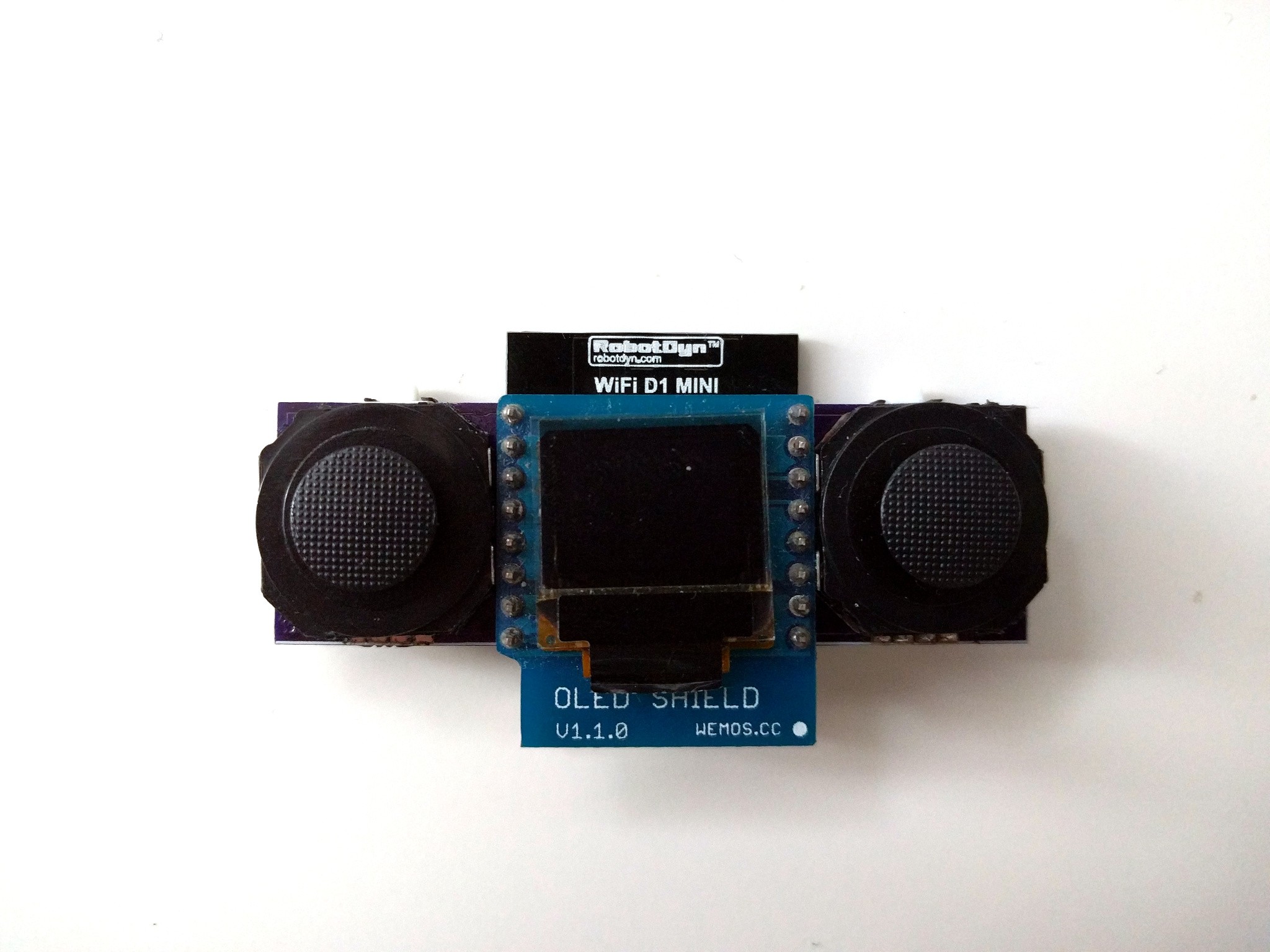
The prototype of the analog joystick shield is now assembled.
I also modified the original firmware to return additional four bytes for the positions of the sticks:
#include "USI_TWI_Slave/USI_TWI_Slave.c"


#define BUTTONS_COUNT 4
#define JOY_COUNT 4
#define INT_PIN 5
#define I2C_ADDRESS 0x11
const uint8_t button_pins[BUTTONS_COUNT] = {8, 2, 9, 10};
const uint8_t joy_pins[JOY_COUNT] = {0, 1, 7, 3};
volatile bool clear = false;
volatile uint8_t buttons = 0;
volatile uint8_t joy_values[JOY_COUNT] = {127, 127, 127, 127};


void request() {
    USI_TWI_Transmit_Byte(buttons);
    for (uint8_t i = 0; i < JOY_COUNT; ++i) {
        USI_TWI_Transmit_Byte(joy_values[i]);
    }
    clear = true;
}

void setup() {
    for (uint8_t i = 0; i < BUTTONS_COUNT; ++i) {
        pinMode(button_pins[i], INPUT_PULLUP);
    }
    pinMode(INT_PIN, INPUT);
    USI_TWI_Slave_Initialise(I2C_ADDRESS);
    USI_TWI_On_Slave_Transmit = request;
}

void loop() {
    static uint8_t last_buttons = 0;
    static bool interrupt = false;
    uint8_t current_buttons = 0;

    for (uint8_t i = 0; i < BUTTONS_COUNT; ++i) {
        current_buttons <<= 1;
        current_buttons |= !digitalRead(button_pins[i]);
    }
    if (clear) {
        Flush_TWI_Buffers();
        clear = false;
        buttons = 0;
        if (interrupt) {
            pinMode(INT_PIN, INPUT);
            interrupt = false;
        }
    }
    buttons |= last_buttons & current_buttons;
    if (buttons && !interrupt) {
        interrupt = true;
        pinMode(INT_PIN, OUTPUT);
    }
    last_buttons = current_buttons;
    for (uint8_t i = 0; i < JOY_COUNT; ++i) {
        joy_values[i] = (analogRead(joy_pins[i]) >> 2) & 0xff;
    }
    delay(16);
}
I throw away 2 bits worth of precision here, because they are mostly garbage anyways, and because it makes it easier to transmit. Initial test looks good:
>>> import machine
>>> i2c = machine.I2C(-1, machine.Pin(5), machine.Pin(4))
>>> i2c.readfrom(11, 5)
b'\x00y\xff\x8a\x88'
But there seems to be a bit of a problem: the right stick returns funky values — the first one is too low, and the second one is always 0xff. A little bit of investigation, and I found the culprit — I didn't connect the ground of that side of the board — both the stick and the button — to the ground of the rest. Nothing a quick bodge can't fix — I added a wire, and now everything works perfectly.
Discussions
Become a Hackaday.io Member
Create an account to leave a comment. Already have an account? Log In.
Glorious!!
Are you sure? yes | no