 Nevyn
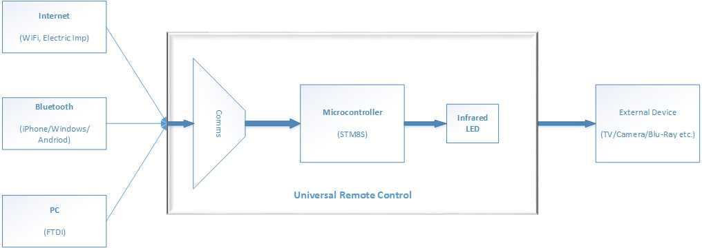
NevynInfrared remote controls use Mr Maxwell's new fangled electrons to generate invisible light and transmit a signal through the luminiferous aether. They do this using a infrared LED, these work very much convention LEDs but in the infrared spectrum. The aim of the project to to make a remote control which is capable of taking commands from a number of sources including the ability to change the command signals transmitted by the remote control. The overall system design is as follows:
The project will start by giving some background theory and building a detector circuit in order to verify that the remote control is functioning as expected.
This project was initially started to build a replacement for a remote control for a Nikon D70 DSLR and the initial work has this goal in mind.
The later stages of the project will add the ability to change the carrier frequency (more of that in the project logs) and the command sequences stored in the remote control.
Finally, the multiple communications/connectivity options will be added to the remote control.
The project overview video can be found on YouTube:


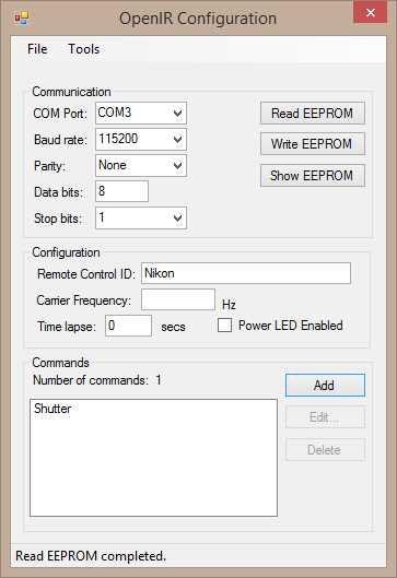
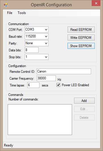
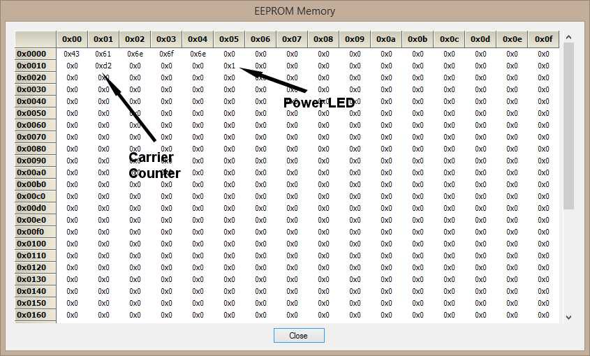
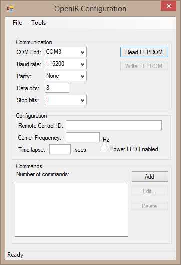 The upper panel allows the user to select the COM port and the communication settings (baud rate, parity etc.). The two buttons allow the user to request the EEPROM data and write send the updated the EEPROM configuration back to the IR remote control module.
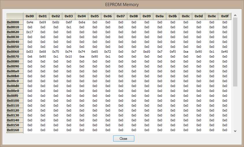
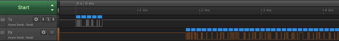 Zooming on on the request trace we can see that the command 1 (request for EEPROM data) is sent to the IR remote control:
 Moving...
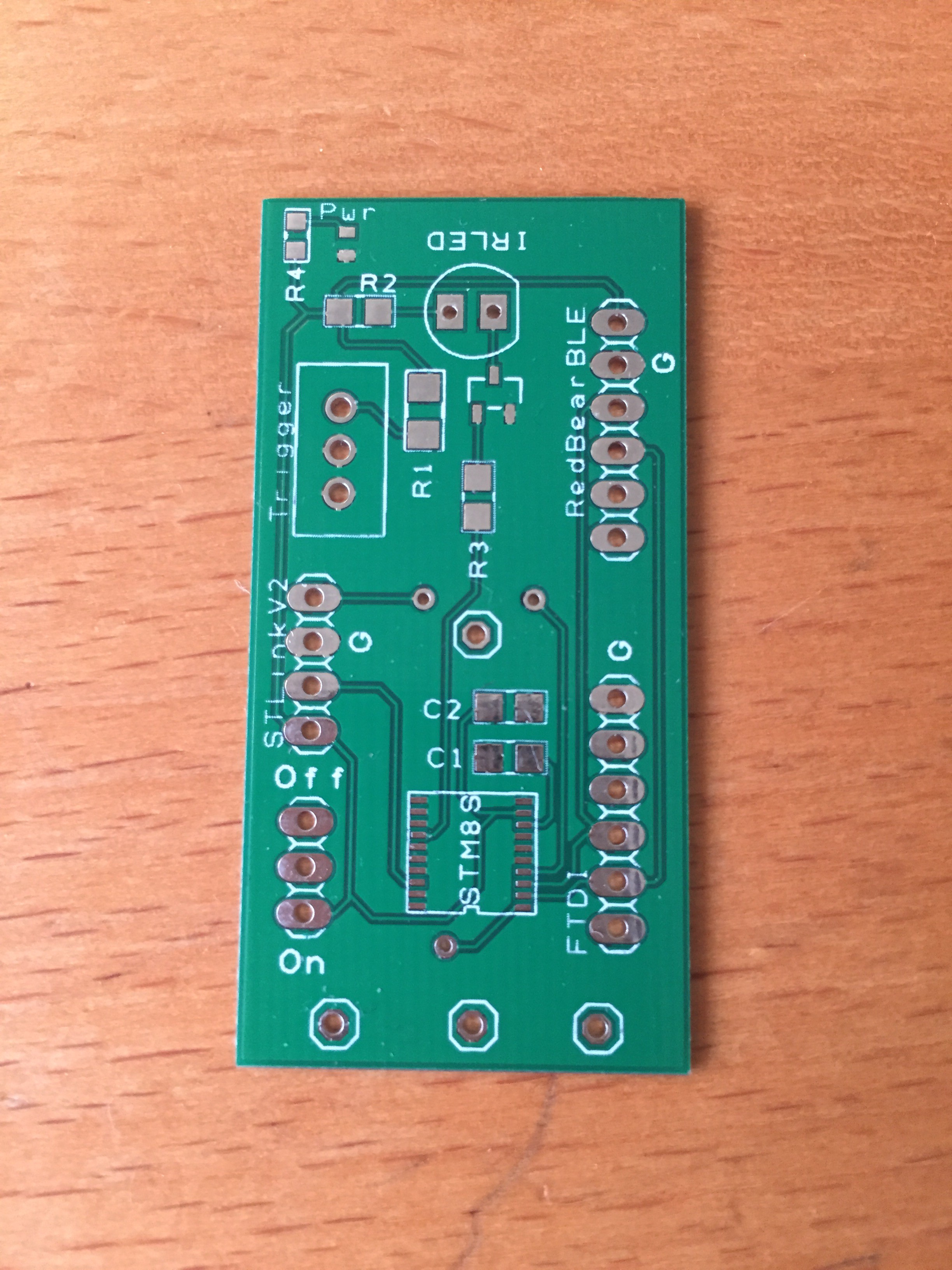
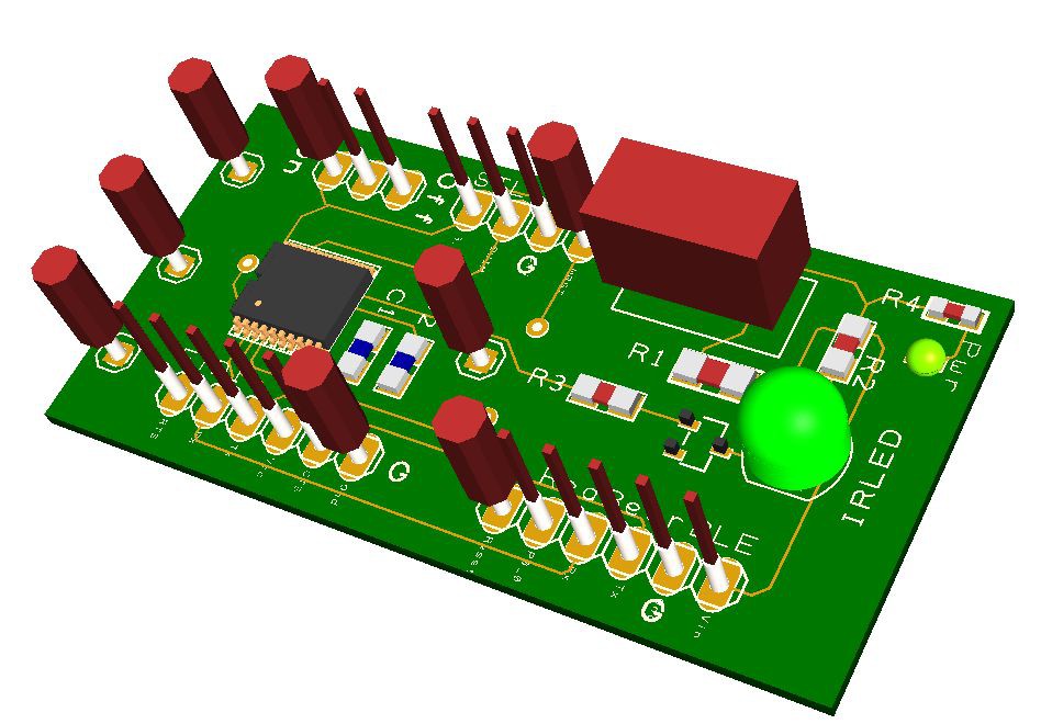
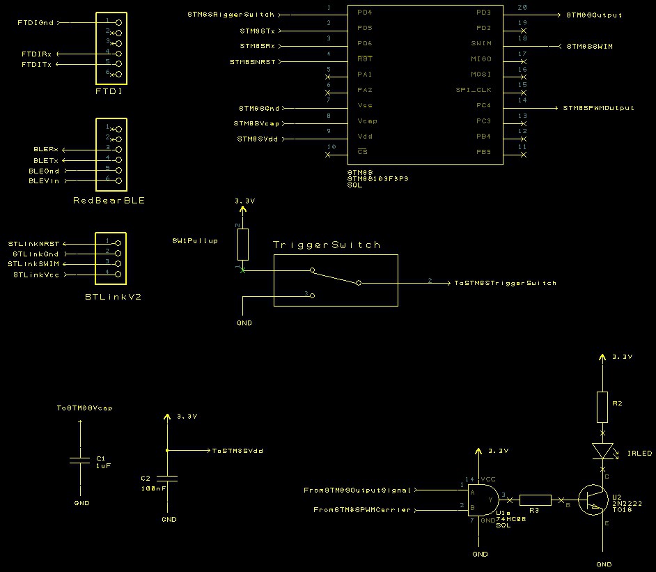 into a working board.
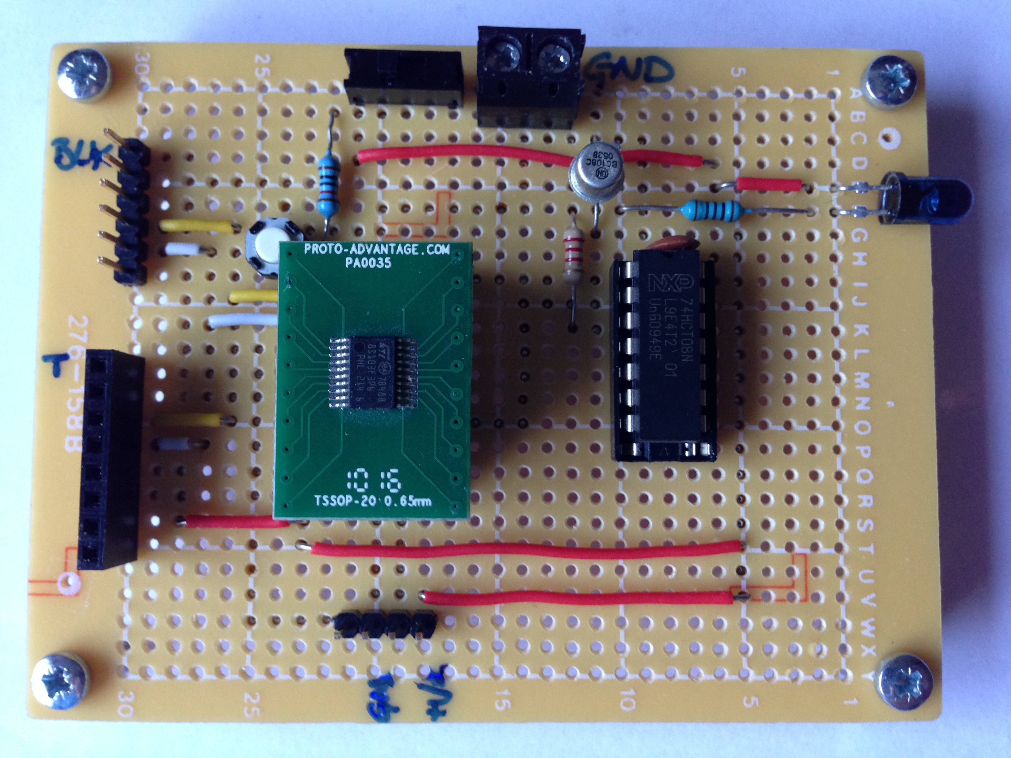 The two connectors to the left of the board are the TTL serial (top male) and RedBear BLE (bottom female) connectors. The connector on the lower part of the board allows the connection of the STLink/V2 programmer to the STM8S.
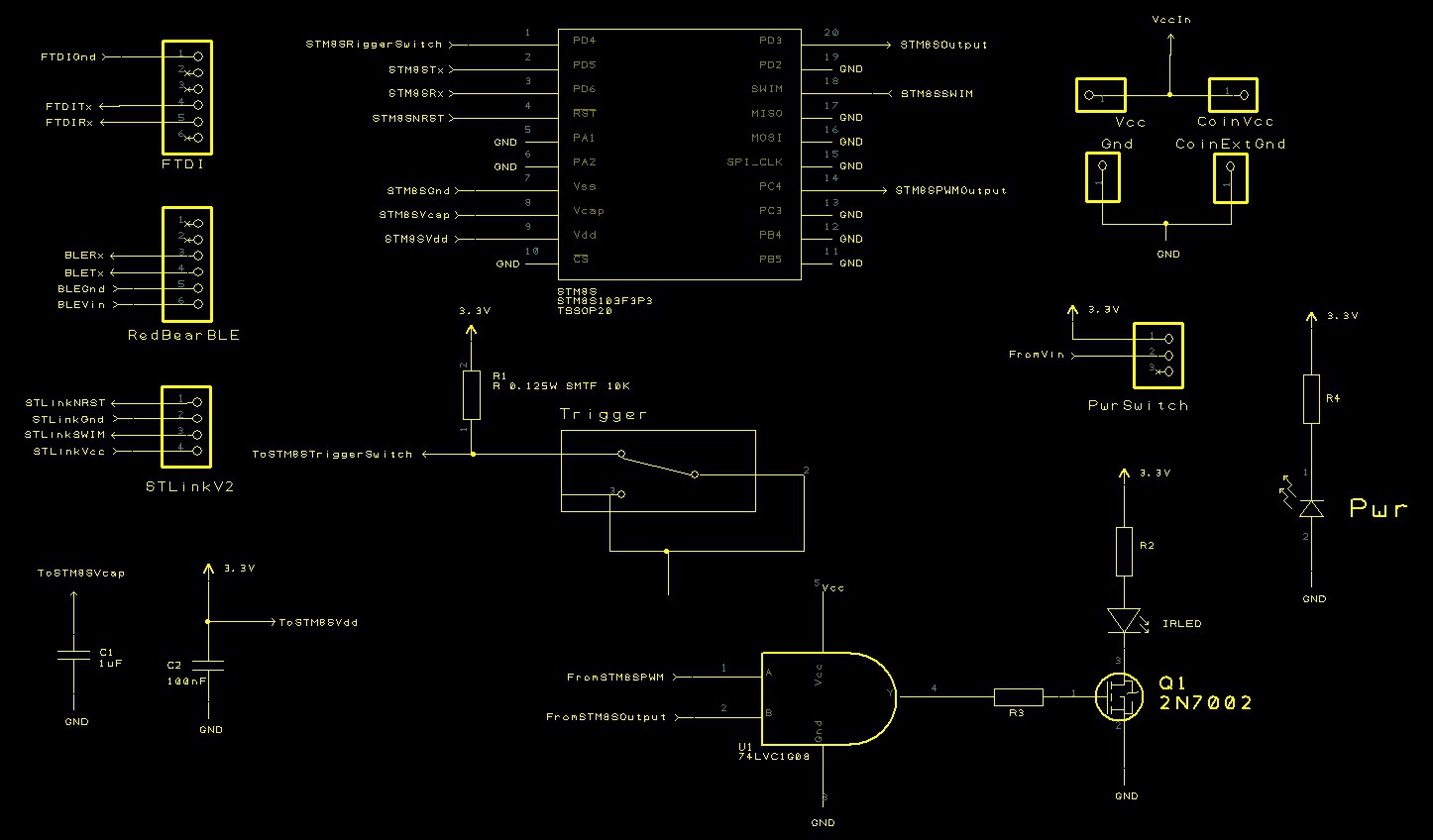 The number of components required is small and should fit on a board which can be made using
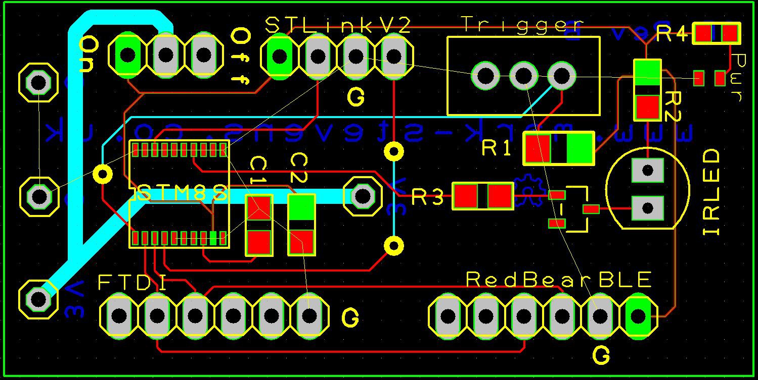
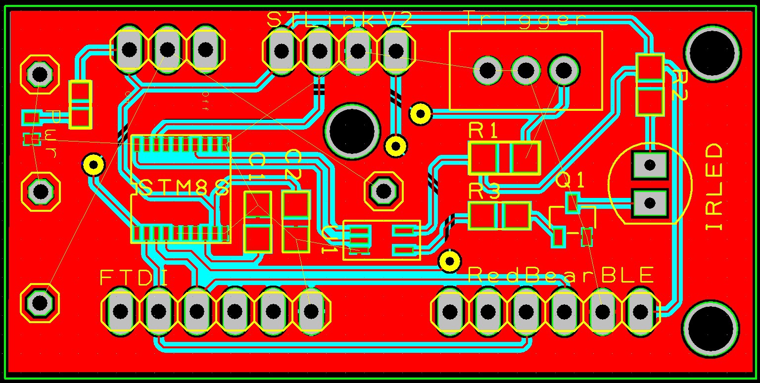 Time to send the board of for manufacture. Next step, software development and assembly.
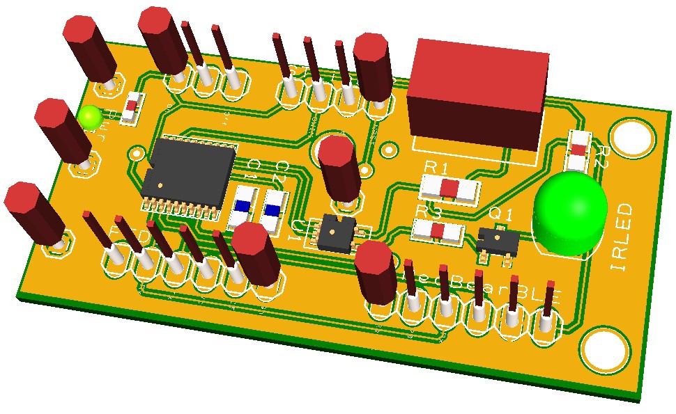
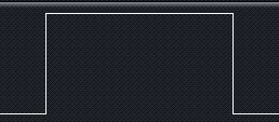
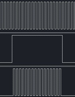 The lower trace shows how the carrier signal is only output when a digital one is to be generated. At all other times the output remains at logic zero.
 A single AND gate is available in surface mount form but a standard 74HCT08 quad AND gate can be used for the prototype.
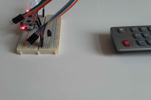
 benedekkupper
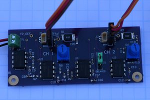
 Bharbour
 Kuldeep Singh Dhaka