 Nevyn
NevynThis step of the projects creates a digital output with the correct timing sequence for a Nikon DSLR. The signal will be unmodulated at this stage with the modulation being added at a later stage..
Background
The Nikon D70 uses the ML-L3 infra-red remote control to trigger the camera. The remote sequence for the Nikon D70 has been investigated before. I found the post by Michelle Bighignoli to be very useful. According to Michelle's post the following sequences of pulses will trigger the camera:
- High pulse for 2000uS
- Low for 27830uS
- High for 400uS
- Low for 1580us
- High for 400uS
- Low for 3580uS
- High for 400uS
Michelle also notes that the modulation frequency is 38.4KHz..
Microcontroller Circuit
The microcontroller selected for this project is the STM8S. This microcontroller is a small device available in a number of formats (memory size, foot print etc.) and is one I have been using for a while now. You can find these available on STM8S Discovery boards costing less than £6 (UK Sterling). The Discovery board contains the STM8S105C6T6 which is one of the larger versions of the STM8S but it also has one other very useful feature, namely the inclusion of the programmer required to program other STM8S chips. The programmer is connected to your PC via USB and gives the same ability as the external stand alone programmer (ST/Link V2) which would otherwise be required.
For this post the STM8S will be used stand alone (non-Discovery board version) in order to prototype from breadboard through to final PCB. The schematic for the basic circuit is as follows:
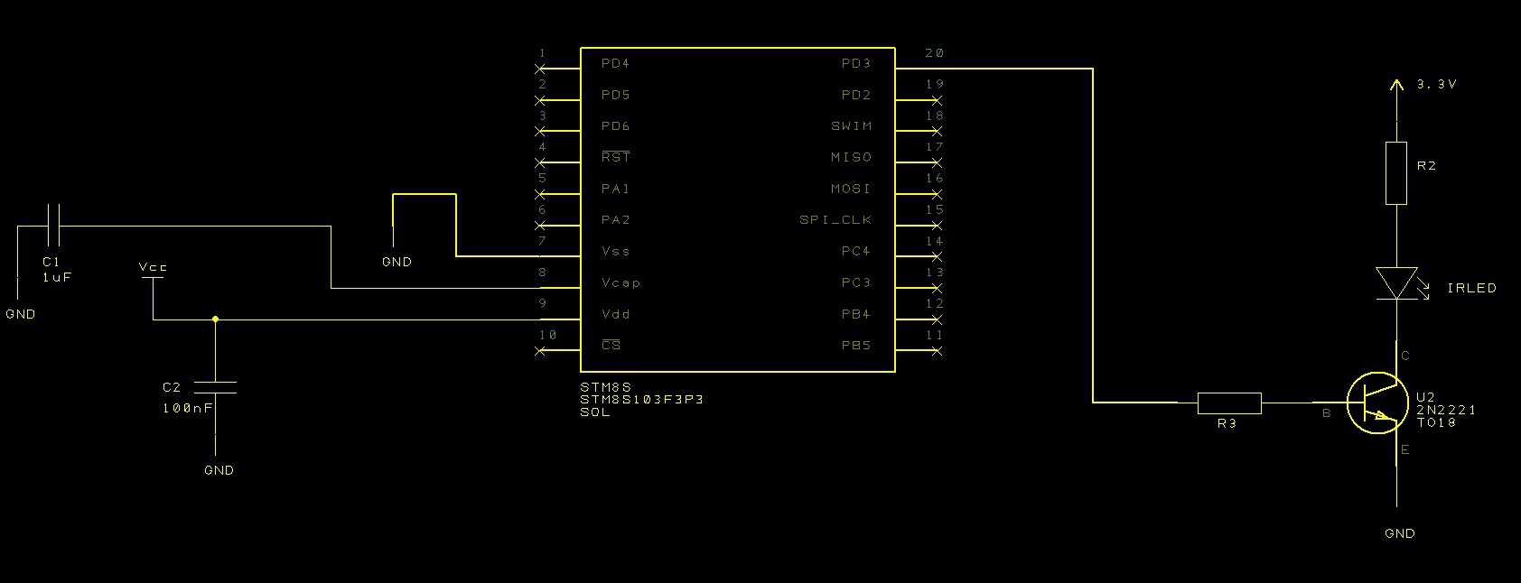 The circuit on the right should look familiar, it is the infrared transmitter circuit built in the previous project log.
The left hand side of the circuit shows the STM8S103F3 and the two components necessary for the microcontroller to function correctly. C1 is a 1uF multilayer capacitor and this is used to regulate the internal clock circuitry. C2 is a 100nF capacitor and is the decoupling capacitor for the microcontroller.
For more information on the STM8S please consult the ST web site. You can also consult the series of posts called The Way of the Register on the authors own blog.
Software
As an initial test, the STM8S will be configured to generate the digital output signal (without modulation) as soon as the STM8S is powered on. This is simple enough for a proof of concept and is something which will be built upon later.
Note that for this project the code will be developed using IAR Embedded Workbench. IAR have a free for personal use version of this software. The compiler is code limited to 8KBytes but this has proven adequate for all of the home development projects which the author has worked on so far.
Looking at the pulse sequence, the application will need to be able to generate infra-red pulses with control down to the micro-second level. The pulse widths are reasonably large, the smallest is 400uS. Taking this into consideration, the default clock speed of 2MHz will be used for the initial version of the application.
The most obvious way of controlling the pulse widths is to use one of the built in system timers. The most obvious choice is to use Timer 2 as we are going to be using the default clock speed and only require an accuracy of a micro-second or so. This will give a count in the range 0-65535 implying that the maximum pulse width will be 65,535uS assuming we use a prescalar of 2 to divide down the clock frequency used by Timer 2 to 1MHz.
The timers use two eight bit values to control the counting. This will require that the 16-bit values we have for the pulse durations will need to be broken down into two parts either before the sequence starts or as the sequence is being generated (i.e. in the timer Interrupt Service Routine (ISR)). The method chosen here is to perform this operation before the first pulse is generated. This will allow for a quicker ISR.
To start we need somewhere to store the pulse information, the applicaiton needs to know the pulse duration and whether the pulse is a high or a low pulse:
unsigned int pulseLength[] = { 2000U, 27830U, 400U, 1580U, 400U, 3580U, 400U };
unsigned char onOrOff[] =    {   1,      0,     1,     0,    1,     0,    1 };
This data will be configure later in the main loop but it is presented here in order to aid the understanding of the following code.
We also need some variables to allow the application to keep a track of where it is in the pulse sequence:
//
//  Data ready for the pulse timer ISR's to use.
//
unsigned char *_counterHighBytes = NULL;
unsigned char *_counterLowBytes = NULL;
unsigned char *_outputValue = NULL;
int _numberOfPulses = 0;
int _currentPulse = 0;
The two counter variables (_counterHighBytes and _counterLowBytes) will store the values which should be written to the counter in order to generate the correct pulse sequence. These are worked out in our next method:
//--------------------------------------------------------------------------------
//
//  Prepare the data for the timer ISRs.
//
void PrepareCounterData(unsigned int *pulseDuration, unsigned char *pulseValue, unsigned int numberOfPulses)
{
    _numberOfPulses = numberOfPulses;
    if (_counterHighBytes != NULL)
    {
        free(_counterHighBytes);
        free(_counterLowBytes);
        free(_outputValue);
    }
    _counterHighBytes = (unsigned char *) malloc(numberOfPulses);
    _counterLowBytes = (unsigned char *) malloc(numberOfPulses);
    _outputValue = (unsigned char *) malloc(numberOfPulses);
    for (int index = 0; index < numberOfPulses; index++)
    {
        _counterLowBytes[index] = (unsigned char) (pulseDuration[index] & 0xff);
        _counterHighBytes[index] = (unsigned char) (((pulseDuration[index] & 0xff00) >> 8) & 0xff);
        _outputValue[index] = pulseValue[index];
    }
    _currentPulse = 0;
}
The method above facilitates the high speed functioning of the ISR. It breaks the pulse duration down into the two values required to be written to the registers which control when the next interrupt will be generated by the Timer.
Setting up Timer 2 should simply be a case of loading the timer with the first set of values for the high and low counter registers, setting the prescalar and then enabling the interrupts:
//--------------------------------------------------------------------------------
//
//  Now set up the output ports.
//
//  PD3 - IR Pulse signal.
//
void SetupOutputPorts()
{
    PD_ODR = 0;             //  All pins are turned off.
    //
    //  PD4 is the output for the IR control.
    //
    PD_DDR_DDR3 = 1;
    PD_CR1_C13 = 1;
    PD_CR2_C23 = 1;
}
At the end of the above method the Timer is configured but not yet running. The _prescalar variable should contain the power of 2 required to scale the internal clock from 2MHz down to 1MHz (i.e. 1). This is defined as a variable to allow for the functionality which will come in future posts.
Now that the timer is configured the interrupt needs to be captured and processed. This is done by the following method:
//--------------------------------------------------------------------------------
//
//  Timer 2 Overflow handler.
//
#pragma vector = TIM2_OVR_UIF_vector
__interrupt void TIM2_UPD_OVF_IRQHandler(void)
{
    _currentPulse++;
    if (_currentPulse == _numberOfPulses)
    {
        //
        //  We have processed the pulse data so stop now.
        //
        PD_ODR_ODR3 = 0;
        TIM2_CR1_CEN = 0;
    }
    else
    {
        TIM2_ARRH = _counterHighBytes[_currentPulse];
        TIM2_ARRL = _counterLowBytes[_currentPulse];
        PD_ODR_ODR3 = _outputValue[_currentPulse];
        TIM2_CR1_URS = 1;
        TIM2_EGR_UG = 1;
    }
    TIM2_SR1_UIF = 0;               //  Reset the interrupt otherwise it will fire again straight away.
}
The first two lines (#pragma and the function prototype) are IAR's way of defining this method as a special method. The two lines together tell the compiler that this method is an interrupt handler and that should be associated with the Timer 2 overflow handler. The first step is necessary to ensure that the preamble for the method preserves the various registers before any code is executed and also that the special interrupt return instruction is executed at the end of the method to restore the registers.
The first part of the if statement works out if we have any more pulse data and if we do not then it turns the timer off. If we still have pulse data (i.e. the else clause) then we reload the timers, set the output accordingly and restart the counters.
The two registers TIM2_ARRH and TIM2_ARRL hold the counter autoreload values. These are 8 bit registers and hold the high and low parts of the counters respectively.
The final method before we look at the main program loop is the one which is required to configure the output ports:
//--------------------------------------------------------------------------------
//
//  Now set up the output ports.
//
//  PD3 - IR Pulse signal.
//
void SetupOutputPorts()
{
    PD_ODR = 0;             //  All pins are turned off.
    //
    //  PD4 is the output for the IR control.
    //
    PD_DDR_DDR3 = 1;
    PD_CR1_C13 = 1;
    PD_CR2_C23 = 1;
}
This method simply configures pin 3 of port D on the STM8S to be a high speed output port.
The final piece of the software puzzle is the main program loop:
//--------------------------------------------------------------------------------
//
//  Main program loop.
//
void main()
{
    unsigned int pulseLength[] = { 2000U, 27830U, 400U, 1580U, 400U, 3580U, 400U };
    unsigned char onOrOff[] =    {   1,      0,     1,     0,    1,     0,    1 };
    PrepareCounterData(pulseLength, onOrOff, 7);
    __disable_interrupt();
    SetupTimer2();
    SetupOutputPorts();
    __enable_interrupt();
    PD_ODR_ODR3 = _outputValue[0];
    //
    //  Now we have everything ready we need to force the Timer 2 counters to
    //  reload and enable Timer 2.
    //
    TIM2_CR1_URS = 1;
    TIM2_EGR_UG = 1;
    TIM2_CR1_CEN = 1;
    while (1)
    {
        __wait_for_interrupt();
    }
}
The first block of code above comment in the main method configures the system and gets the timer ready to run. The three lines under the comment start Timer 2 running.
The while loop merely does nothing but wait for an interrupt. When an interrupt fires it simply waits again. This continues ad-infinitum.
Conclusion
Putting the hardware together and programming the microcontroller results in the following output on an oscilloscope connected to pin 3 of port D on the STM8S:
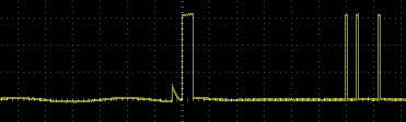 Examination of the timing between the pulses and the duration of the pulses themselves show that they match the specification set out at the start of this log.
The next step is to add some signal modulation.
Discussions
Become a Hackaday.io Member
Create an account to leave a comment. Already have an account? Log In.