 Alan Penner
-
1Step 1
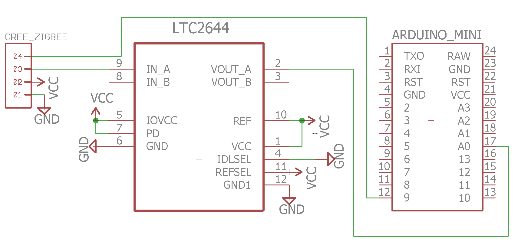
Wire the Cree Zigbee board to the LTC2644 and Arduino as shown in the schematic or picture. Note that pin 1 on the Cree board is towards the middle of the board, and pin 4 is towards the outer edge.
Everything is currently powered by the USB to TTL programmer connected to the Arduino, but a 3.3v regulator would work as well. I bring VCC and GND out from Arduino pins 4 and 21 to my breadboard power bus.
- Zigbee board pin 1: GND
- Zigbee board pin 2: VCC
- Zigbee board pin 3: LTC2644 pin 9 (IN_A)
- Zigbee board pin 4: Arduino digital input 9 (pin 12 on the Arduino Pro Mini)
The LTC2644 wiring:
- Pin 1: VCC
- Pin 2: Arduino analog input A0 (pin 17 on the Arduino Pro Mini.) This is the analog output converted from the PWM signal.
- Pin 3: Unused
- Pin 4: IDLSEL to GND. Prevents DAC from powering down if there is no PWM signal for a while.
- Pin 5: IOVCC to VCC. Voltage level of the I/O input supply.
- Pin 6: GND
- Pin 7: VCC to put the chip in normal operation mode instead of a power-down mode.
- Pin 8: Unused.
- Pin 9: Zigbee board pin 3. This is the PWM signal from the Cree bulb board.
- Pin 10: VCC for reference voltage. The DAC scales the analog output with this reference as the maximum voltage.
- Pin 11: VCC. Tells the DAC to use pin 10 as the reference voltage instead of an internal reference.
- Pin 12: GND
![Schematic]()
![Circuit]()
-
2Step 2
Flash the Arduino with the following sketch. This is also included as a file attached to the project.
int last_level = 0;
bool last_state = false;
bool stable = false;
int count = 0;

const int cutoffs[198] = {/* 1*/ 833, 831, /* 2*/ 825, 823, /* 3*/ 817, 816, /* 4*/ 809, 808, /* 5*/ 801, 800,
                          /* 6*/ 793, 791, /* 7*/ 785, 783, /* 8*/ 773, 771, /* 9*/ 769, 767, /*10*/ 757, 755,
                          /*11*/ 753, 751, /*12*/ 741, 739, /*13*/ 733, 731, /*14*/ 725, 723, /*15*/ 717, 716,
                          /*16*/ 709, 708, /*17*/ 697, 695, /*18*/ 693, 691, /*19*/ 681, 680, /*20*/ 677, 675,
                          /*21*/ 665, 664, /*22*/ 661, 659, /*23*/ 649, 648, /*24*/ 641, 640, /*25*/ 633, 632,
                          /*26*/ 625, 624, /*27*/ 617, 616, /*28*/ 605, 604, /*29*/ 601, 600, /*30*/ 589, 588,
                          /*31*/ 585, 584, /*32*/ 573, 572, /*33*/ 569, 568, /*34*/ 557, 556, /*35*/ 549, 548,
                          /*36*/ 541, 540, /*37*/ 533, 532, /*38*/ 525, 524, /*39*/ 513, 512, /*40*/ 509, 508,
                          /*41*/ 496, 496, /*42*/ 493, 492, /*43*/ 480, 479, /*44*/ 477, 472, /*45*/ 464, 463,
                          /*46*/ 456, 455, /*47*/ 448, 447, /*48*/ 440, 439, /*49*/ 432, 431, /*50*/ 420, 419,
                          /*51*/ 416, 415, /*52*/ 404, 403, /*53*/ 400, 399, /*54*/ 388, 387, /*55*/ 380, 379,
                          /*56*/ 372, 371, /*57*/ 364, 363, /*58*/ 356, 355, /*59*/ 348, 347, /*60*/ 340, 339,
                          /*61*/ 332, 331, /*62*/ 324, 322, /*63*/ 312, 310, /*64*/ 308, 307, /*65*/ 296, 295,
                          /*66*/ 287, 287, /*67*/ 280, 279, /*68*/ 271, 271, /*69*/ 263, 263, /*70*/ 255, 255,
                          /*71*/ 247, 246, /*72*/ 239, 238, /*73*/ 231, 230, /*74*/ 223, 222, /*75*/ 215, 210,
                          /*76*/ 204, 202, /*77*/ 196, 194, /*78*/ 188, 186, /*79*/ 179, 178, /*80*/ 171, 170,
                          /*81*/ 163, 162, /*82*/ 155, 154, /*83*/ 147, 146, /*84*/ 139, 138, /*65*/ 131, 130,
                          /*86*/ 119, 118, /*87*/ 115, 114, /*88*/ 103, 102, /*89*/  95,  94, /*90*/  87,  86,
                          /*91*/  79,  78, /*92*/  71,  70, /*93*/  63,  62, /*94*/  55,  54, /*95*/  47,  42,
                          /*96*/  39,  38, /*97*/  27,  26, /*98*/  23,  22, /*99*/  11,  10 };

void setup() {
  Serial.begin(115200);
  pinMode(A0, INPUT);
  pinMode(9, INPUT);
}

int getlevel(int value) {
  if (value == 0) return 100;
  if (value > 900) { return 0; }
  for (int i = 0; i < 198; i+= 2) {
    if (value <= cutoffs[i] && value >= cutoffs[i+1]) {
        return (i / 2) + 1;
    }
  }
  return -1;
}

// the loop function runs over and over again forever
void loop() {
  int level = 0, dimlevel = 0;

  /* read on/off status from Cree board */
  int state = digitalRead(9);
  if (state != last_state) {
    Serial.print("Bulb switched to: ");
    Serial.println(state ? "ON" : "OFF");
    last_state = state;
  }

  for (int i = 0; i < 5; i++) {
    level += analogRead(A0);
    delay(5);
  }
  level /= 5;

  dimlevel = getlevel(level);
  if (dimlevel == -1) { return; }
  if (dimlevel != last_level) {
    last_level = dimlevel;
    count = 0;
    stable = false;
  } else {
    count++;
    if (count > 4 && !stable) {
      Serial.print("Level changed to: ");
      Serial.println(dimlevel);
      stable = true;
    }
  }
}
Cree Dimming Level
Getting discrete dimming level value out of the Zigbee board from a Cree Connected Bulb.

Discussions
Become a Hackaday.io Member
Create an account to leave a comment. Already have an account? Log In.