 Ken Kaiser
Overview
A 3D printed strain wave gear, using a HTD 300-5M-20 and 608 bearings. The belt has 60 teeth, for 30 revolutions of stepper the outer gear rotates once, resulting in a -30:1 gear ratio.
Bill of materials
| Material | Quantity | Dimensions |
| HTD belt | 1 | 300-5M-20 closed loop, 300mm circumference, 5mm tooth pitch, 20mm wide |
| bearings | 4 | 608, OD 22mm outer diameter, ID 8mm core, and 7mm wide |
| 3D printed | 1 | PLA, not the best material, but forgiving |
| set screw | 2 | 3mm nuts with set screws |
| snap ring | 2 | 8mm |
| stepper | 1 | nema 17 |
| screws | 4 | M3 screws to attach stepper to gear |
Design
Using the parametric design I printed exactly the STL output. The parametric model was designed and mainly checked against an HTD 300-5M-20 that I used here. I added space for nuts on the wave generator and set screws. To assemble the wave generator 3D-printed pins for the bearings with a spot for snap rings.
|
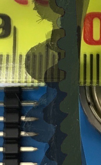
HTD Belt | Tooth spacing / depth |
|---|---|---|
| 8M | 8mm / 3.38mm | |
| 5M | 5mm / 2.06mm | |
| 3M | 3mm / 1.17mm | |
| The picture shows the belt teeth against a millimeter tape. So far is seems that 3M belts require the gear to be too precise and don't deal with forces, 5M seems like a good mix for prototypes. |
Using a 20mm wide belt, gear parts should be less than 10mm each when the sides are assembled there isn't friction between the two halves.
Control
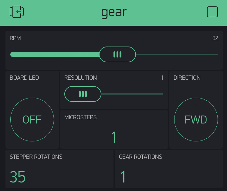
I used a Arduino MKR1000 using the Timer5 library, controlled by the Blynk app. The sketch controlled a DRV8825 stepper module. I can make details available upon request. Here is the configuration of the Blynk app:
Measurements
Torque
I can feel there is more torque on the gear output. What is an effective way to measure torque? I have 5M and 8M and belts of different diameters.
Current
I would want the stepper speed and current to the controlled/captured at the same time. A current sensing resistor supplying the input of an op-amp, conditioned, then captured by the ADC, should work but is there an easier/better way?
Resolution
A laser diode mounted on the gear output pointed at a wall would allow measurements to find the effective repeatable resolution. Then finding out what force results in what loss of resolution or repeatability.
Discussions
Become a Hackaday.io Member
Create an account to leave a comment. Already have an account? Log In.
Great project log Ken! Torque (and probably angular resolution) will be difficult to isolate, let alone measure, until the output gear is more constrained than it currently appears to be. The mechanical arrangement has been one thing that has slowed me down in getting my next iteration up and running.
Presently, I'm wondering about a sandwich of three gear rings, with the outer two matching. Still need to overcome friction/play from slewing forces. Hmmm.
Are you sure? yes | no