 PK
PKThe Executive Summary
- Version 1 is done! Get everything you need through the links here to build your own.
- 640x480 Video @ 8 bit color over SPI.
- 5v, 3.3v, 2.5v SPI Tolerant (Power it with 5v though!)
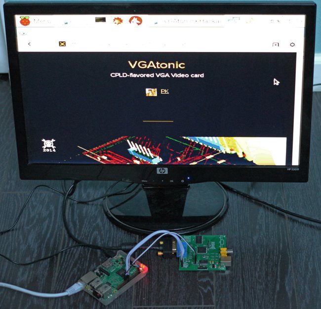
- Framebuffer driver for Raspberry Pi 2 Model B using 62.5 MHz SPI, 25 frames per second at full glorious 640x480x8bpp (see screenshot and movie!).
- Example driver code for Arduino (Intel Galileo Generation 1 Board). (Also can work on a regular Arduino if you don't need to store 640*480*8 bits in the code)
The Engineer's Report
As there are a number of interesting "display-driver-less" dev boards and embedded linux products on the market nowadays (not to mention the 3 PogoPlugs and the Intel Galileo and Edison in my own parts bin), I set out to find a solution for getting reasonable video out of the world's collection of headless parts. Along the way I built a framebuffer for the Raspberry Pi 2 Model B (headless, but not display-driver-less!) as well due to the great ecosystem... and the tons of prior art!
VGAtonic v1 was my effort to make said headless parts connect to the displays people already have lying around - monitors and TVs with VGA input.
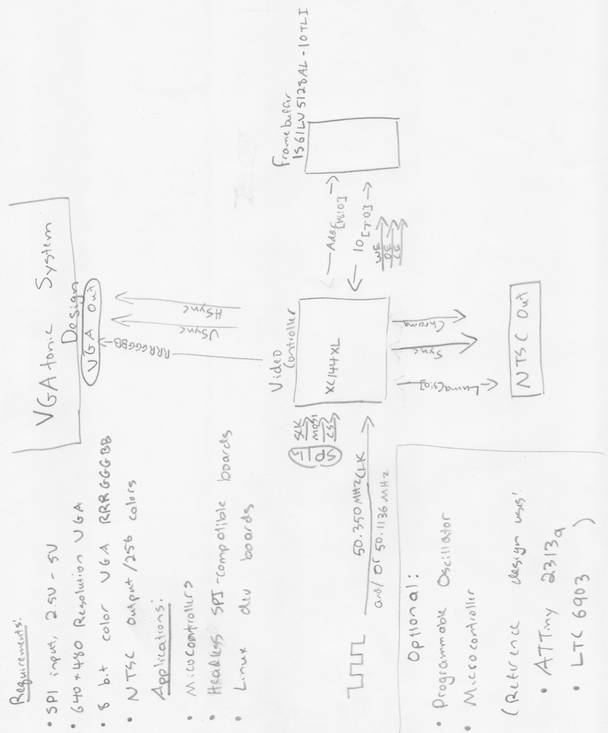
Our goal was modest - 640x480 is still the fallback, worst case resolution for lots of applications - so we'll target VGA's original 640x480 spec. Technically, the original VGA asked for just 4 bit color (read: 16 colors), but as an analog protocol we'll double the number of bits to 8 to get 256 colors.
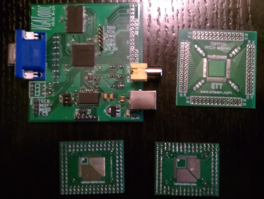
For the brains, we used a 4MBit ISSI IS61LV5128AL-10 with a Xilinx XC95144XL CPLD providing the brawn and the timing. Our first reference design, a roughly 3"x3" PCB, was already released, and we decided to use a programmable oscillator (Linear Technology's LTC6903) and a microcontroller (Atmel's ATTiny 2313a) for board support and experimentation.
BOM is roughly $23-$32 a board depending on your skill and experience (I went 3.5 out of 5, the .5 works with some pin remapping so I got lucky).


 Ross Bamford
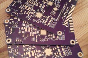
 Eric Hertz
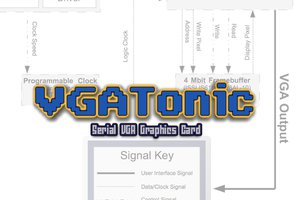
I'd love to see this Saturation based image format implemented in hardware, https://r0k.us/graphics/png16Tech.html#fc16