 PK
PKSorry for the info dump the other day; I didn't have time to write up something real.
But, seriously, PCBs were ordered - why be mad? Let's start with pictures of my reference design, and talk about what I added, what I could/should have done better, and why I made some choices.
But first, a picture of the top of the PCB and a render, of course!
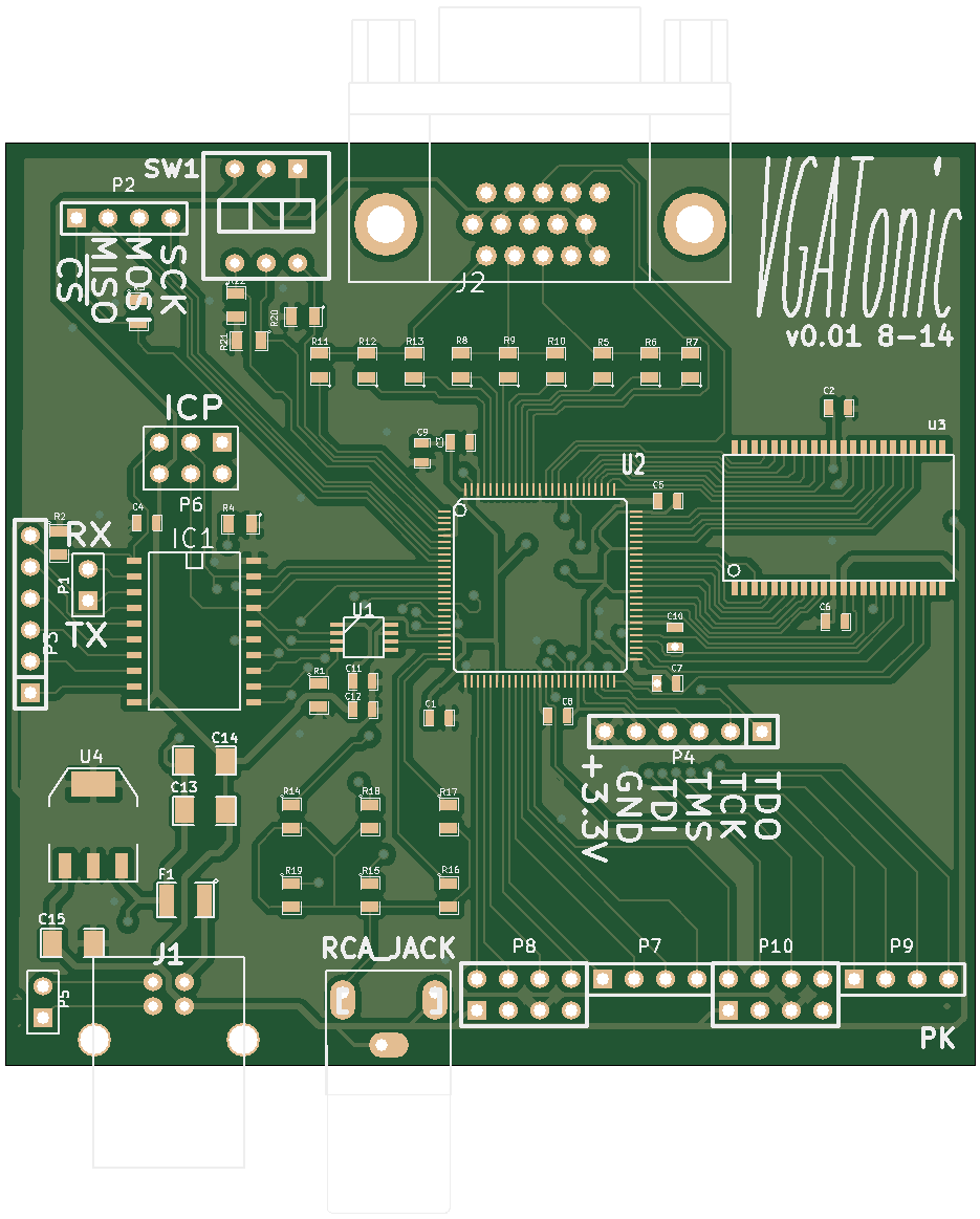
PCB Top with Silkscreen
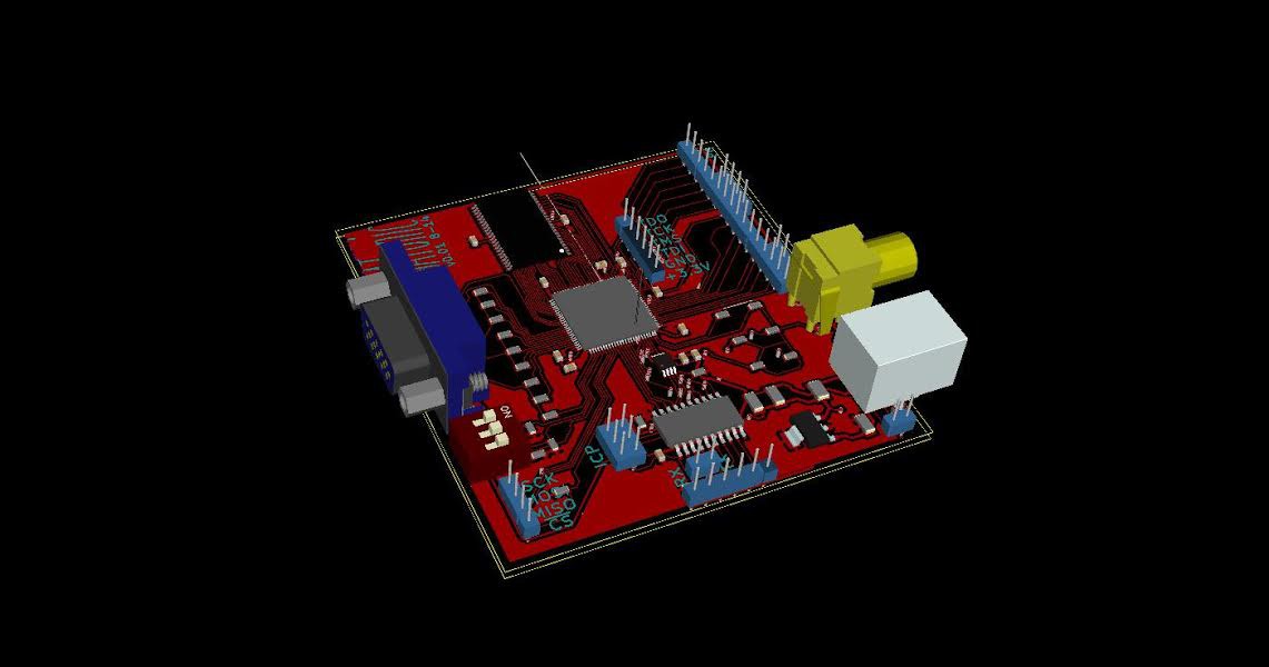
Rendering of VGAtonic from Kicad
So, What's New?
Tons... at least compared to the working demo. You'll note that we've added the XC95144XL now, and I'll stop playing with the 64 and 72 macrocell poseurs. We've added the memory I discussed two posts ago, the ISSI IS61LV5128AL-10. I've added an LTC6903 programmable oscillator to play with the clock, and, because it's almost always a good idea, I added a microcontroller (AVR ATTiny 2313a) with a few extra lines routed to the CPLD for whatever fun features we dream up.
I also, of course, made a basic power supply. Power comes in through the USB-B jack, goes through a PTC, then into a basic 3.3v regulator, ON Semiconductor's NCP1117ST33T3G.
For decap, I just used X5R .1uF capacitors near the power pins, all on the topside for ease of assembly. The '6903 got an extra 1uF capacitor too, for good luck. There are a couple others near the power supply (2x 10uF and a 47uF) - see my schematic in the git repo for details.
So, What Could Be Better?
Well, for one, I had no size in mind - I want it to roughly fit in a 4x6 picture frame, *maybe*, so I ended up with 3"x3". I think it might make more sense to aim for something real - I've heard some rumblings of DIP compatible, so maybe a future version should "barely fit on a breadboard". You tell me.
Second, I left vias in some pads - I thought I moved those, but the design doesn't lie. I'm not to worried about my solder bleeding through the holes though because for the passives I'll be hand soldering using leaded paste.
Third, for some reason my VGA footprint doesn't have anything exposed on the backside to solder too. This won't be a huge problem though: just flood it so the solder flows to the other side.
Fourth, (nitpicky) the RCA jack's alignment post hangs off the board. It would be better to have left something for it to stay on.
Fifth, I probably should have done better with that ground plane - but at only 50 MHz, I'm not too worried about it. I'll eat those words if I can't get any output, of course, but for a first draft it'll do.
Why Did You Do _______?
Obviously, I made a few game-time decisions here - adding the programmable oscillator and AVR will help with the prototyping and firmware, and the extra routes from the ATTiny might come in handy for something.
For I/O I had plenty of extra pins. I routed 3 to DIP switches, and I made a Papilio compatible Wing ( http://papilio.cc/ )... so you can add whatever you want to this and use it like a normal CPLD breakout if you want. Or, you know, add 2 more VGA ports to your VGA controller so you can VGA while 2x VGAs.
USB power was because I have a ton of USB-B cables and computers and chargers to plug them into. I suppose I could have used a typical barrel jack, but... it'll be fine (and I didn't want to bother with a 5v regulator).
Also, you'll notice the resistor ladder for VGA grew by one - RRR GGG BB and a third B. We'll use the last B if we want to get true greys and white - so technically, we'll have 512 colors to play with (but everything will be 8 bits wide, so we'll have to make some cuts).
All in all, I'm happy with the first effort - let's get a picture on it now, shall we?
Discussions
Become a Hackaday.io Member
Create an account to leave a comment. Already have an account? Log In.