PK
PK-
The Loose Threads in 2015
09/20/2015 at 02:57 • 0 commentsHey folks, lots of new stuff posted over at the 2015 log of VGATonic.
I recently pushed a couple alternate firmwares:
- One for 848x480 (and 424x240) VESA compatible 16:9 output
- One for 320x240 in 16 color NTSC
Go check it out if you're still following along; we've even got a second revision of the board which is much smaller!
-
More Platform Support for VGATonic
07/18/2015 at 00:56 • 0 commentsIf you're still following, note that incremental updates have been moved to my log for the 2015 Hackaday Prize.
I wanted to update you today, however, with some of the major changes you can find over there now:
- Examples/Driver Support for Multiple Platforms
- Arduino
- Raspberry Pi
- Beaglebone Black
- Odroid C1
- 4 Hardware Accelerated Resolutions:
- 640x480
- 320x240
- 160x120
- 80x60
- 4 Hardware Accelerated Bit Depths:
- 8 bits (256 colors)
- 4 bits (16 colors)
- 2 bits (4 colors)
- 1 bit (B&W)
I hope to have some updates for you very soon on the asynchronous serial side, along with an update on the Linux Driver side for the Intel Edison. Stay tuned, preferably on the newer one! (I'll continue to update here, but updates will be slower, of course.)
- Examples/Driver Support for Multiple Platforms
-
Declaring VGATonic v1 Finished.
06/14/2015 at 23:26 • 0 commentsI felt bad about leaving you folks in a weird quasi-finished 98.4% done state. My motivation recently came back so I finally finished a framebuffer implementation for the Raspberry Pi 2 Model B. That's right - "startx" in all of its glory on this part we dreamed up a year ago.
(If that doesn't bring a tear to your eye, maybe that 1994-era color depth will!)
So, if you remember, the big doubt when starting the project was whether we could even fit all our logic on a CPLD. We did it - and we have like 30 macrocells to spare(!) on this 144 macrocell part.
Okay, fine, maybe I just wanted the challenge of the small part, but even though I had the project working well as a "Digital Picture Frame" 10 months ago... I had to see what we could do attached to real equipment.
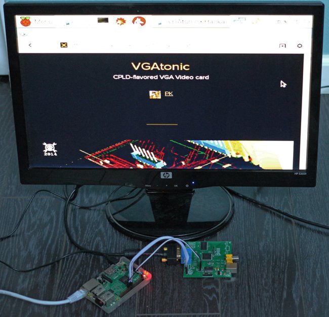
I heard you guys like VGA, so here's VGATonic opening the VGA project VGATonic's project log page and running on a VGA monitor. At 25 frames per second:
![]()
So, hurry over to GitHub and build yourself a copy: https://github.com/dqydj/VGAtonic
And what now? The motivation continues! Parsing the Hackaday Prize 2015 Rules, I see we can build on what we've got since we didn't make the Semifinals cut! Here are the caveats:
1. A new project page must be created
2. The project must show meaningful development during the course of the Contest.
So, let's move this party to the new page: VGATonic v2.0 promises to be a great time. I'll upload a video there soon so you can see it.
This time I'll try to add all the features this year, okay? No waiting until 2016.
-
Working Example Code for the Intel Galileo (Arduino Mode)
09/03/2014 at 03:15 • 0 commentsI wanted to share some working code for the Intel Galileo board I've been showing in my videos. With this update I'm declaring partial victory over this project, because now you can at least reproduce what I've shown in the videos.
Enjoy!
https://github.com/dqydj/VGAtonic/tree/master/First_Draft
Motivation has waned a bit, but here's where I plan to go with this before I hit my 100% wish list:
- User Mode in Linux (Done! Just need to make a formatting/commenting effort and pull it off the Galileo)
- Kernel Module / Framebuffer in Linux (This is the big one - in progress...)
- NTSC Output activated (Not started)
- Add features to CPLD firmware (Not started)
-
Breakout Boards for .5mm TQFP ICs
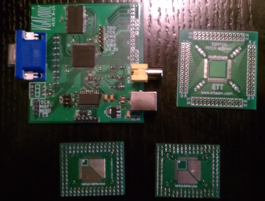
09/03/2014 at 02:41 • 0 commentsIn response to a question in the comments by mylistgroups12, I wanted to show two of the breakout boards I acquired when starting this project. I should note: I originally thought I might fit everything into a smaller CPLD (recall this post), which was in a 64 .5mm QFP size. Still, I got a few breakouts which support the larger, 100 pin size - but even with the 64 pin broken out (I did 5 to practice with the smaller CPLD, but only added pins to one) it was tedious to wire Vcc/Vss.
![]()
In the top right, of course, you can see VGAtonic - roughly 3" x 3", for scale.
In the upper right is a breakout board I bought from Futurlec: http://www.futurlec.com/ (Currently: select 'Components' at top, then on the left 'Sockets', 'SMD Adapter'). It can only support an 100 pin chip, but it makes the pins easier to use/count.
On the bottom is both sides of an adapter I bought on ebay from user e-sale2010. I'd try searching 'QFP Adapter' - but this is nice because you can use anything from 32 - 100 pins in the .5mm pitch. However, the pin count will be funky - I had to make a spreadsheet to convert the labeled pin number to the actual pin number on the CPLDs.
Hope this helps!
-
CPLD Firmware Uploaded!
08/29/2014 at 15:57 • 0 commentsThe moment that a few of you have been waiting for - a glimpse at my VHDL - is now here. See the newest code in our git repo: https://github.com/dqydj/VGAtonic/
You'll want to bring that into ISE Webpack and synthesize it. I've been programming my CPLDs using a Bus Pirate; you can see that methodology here.
Look in this directory for all of the demo code and design documents so far: https://github.com/dqydj/VGAtonic/tree/master/First_Draft
The How to Use file details how this protocol works - it's very simple, I promise.
I'll be back soon with firmware for the ATTiny onboard VGAtonic's reference design, along with the client code used in the Youtube demo.
-
The Game Goes On
08/26/2014 at 16:01 • 0 commentsThis weekend saw 0 progress made on VGAtonic while I was in LA for an event - and, unfortunately, VGAtonic didn't make the semifinals cut for the Hackaday prize.
Don't worry about VGAtonic, though - I'll be following through (even if I don't hew as closely to the original guidelines). I would hate to leave the Pogoplugs and the Galileo headless at this point!
I'll be cleaning up my beta code and adding comments, so look for two pieces of firmware (the microcontroller and the CPLD onboard VGAtonic) and the Galileo code I showed running the demo - well, with more generic pictures. I'll also add the python script I used to create my header files.
Other Graphics Projects
On the other end of the spectrum from VGAtonic, I hope you'll check out GPL-GPU... which is, like stated, a full GPU. Open sourced. I hope you'll check that project out if you'd like a look at a fully-featured graphics controller.
I also read with great interest Andy Brown's recent article about creating a sprite-based video controller on a Xilinx Spartan 3 FGPA. I think you'll find his choice of RAM very interesting if you follow this project!
Stay Tuned!
We'll be back with more updates in the near future - follow us here or on our git repo! -
The Project Deadline Limbo
08/21/2014 at 05:12 • 0 commentsI couldn't resist one last update before the project entries lock... and it's a big one:
That's right; I've got a working prototype here.
640x480 8 bit color VGA video is possible in a 144 macrocell CPLD (spoiler alert: it's possible on an 109 macrocell CPLD or less, actually). Bitmap conversion is done with a Python script, preprocessing was in Adobe Photoshop.
On the technical side, it wasn't immediately evident how to jam 7 bitmaps into Arduino header files. So, here's how to increase your sketch size if you've got a Galileo.
How to Increase Sketch Size on an Intel Galileo (on a Mac)
Getting 7 images to fit in an Intel Galileo Arduino sketch was a bit of a feat - but know this: the default sketch maximum size is a lie!
On my Mac, I was able to change it by right clicking the IDE in my Applications folder, choosing 'Show Package Contents', then 'Contents' -> 'Resources' -> 'Java' -> 'hardware' -> 'arduino' -> 'x86' -> 'boards.txt'.
Here's what I changed the Galileo I section to:
##############################################################

izmir_fd.name=Intel® Galileo
izmir_fd.upload.tool=izmirdl
izmir_fd.upload.protocol=sam-ba
izmir_fd.upload.maximum_size=29491200
izmir_fd.upload.use_1200bps_touch=false
izmir_fd.upload.wait_for_upload_port=false
izmir_fd.upload.native_usb=false


izmir_fd.build.mcu=i586
izmir_fd.build.f_cpu=-m32
izmir_fd.build.core=arduino
izmir_fd.build.variant=galileo_fab_d
#izmir_fd.build.variant_system_lib=libx86_izmir_gcc_rel.a<br>
The important part being that 'maximum_size', of course - by default it's set to 262144 bytes. 640*480 pixels (each with a byte of color info)? 307,200 bytes. So, yeah, it was kind of arbitrary - and worse, you can't even fit one whole bitmap.
But it's not completely arbitrary - you'll get spurious errors in your Arduino IDE once you make the change (or maybe only because I used such a big number?), so save (a lot) more often.
A Working Prototype!(!!)
I know the focusing was pretty bad in the video, but the picture isn't perfect and there are some improvements I'll be making before I release any code. I've got it writing to RAM every cycle: an unnecessary ~9.5ns /WE assertion zooming around the board and upsetting the rest of the PCB. I'll clean that up and put code up on the repo soon (find it in our info section).
But, hey, doesn't that look great? And, even at only 8.33MHz SPI it's not too painful of a refresh. I'll see how we can do with a Linux framebuffer and improved firmware.
Stay tuned, and thanks for following!
-
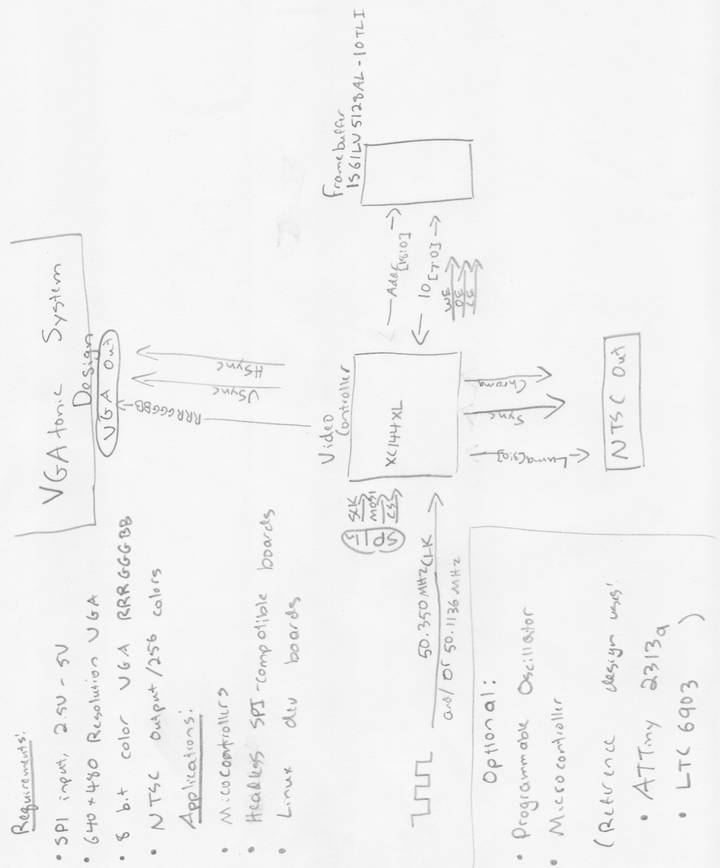
Ticking the Prize Boxes (and the System Design Document)
08/20/2014 at 03:59 • 0 commentsI'm trying to tick off all the boxes before the Hackaday Prize deadline tomorrow - you should be able to find sample code in VGAtonic's git repo (license: MIT), an introduction video, a prototype video (VGA/NTSC), some pictures, and a BOM.
The connectedness portion of the project comes from two directions:
- SPI - literally a peripheral communications protocol (well, maybe a loosely defined generally accepted language, anyway - it's like digital slang)
- Graphics - VGA and NTSC for the screens
- And Bonus #3 (for the philosophers!) - Aren't meaningful graphics really just one way for humans to interact with machines?
The one thing I think I'm lacking is an overall design document, so I drew something up with my "I'm-usually-typing-not-writing" penmanship:
![]()
Really, it's not that complicated of a document - I've mostly been a software guy in industry, so my magic, if I actually have any, comes in the code.
"Hardware without software just generates heat." - Doug Fisher
I won't tease it too much tonight, but I've got something else for you folks before the entry deadline - stay tuned, and thanks for following!
-
Breaking Down the BOM, Costs per Board
08/16/2014 at 16:45 • 0 commentsLet's talk about costs - because when you buy parts in the quantities I am, it's hard to determine exactly what the cost per board is (although we can try).
Part Name #/Board Cost/Part Cost/Board Quantity Purchased Where? Part Number ATTiny 2313a 1 1.11 1.11 10 Newark 68T3554 Bourns PTC Reset Fuse 1 0.134 0.134 10 Newark 83K0399 47uF Tantalum 1 0.4029 0.4029 10 Newark 60R5862 LTC6903 1 3.33 3.33 5 Newark 57M0173 10uF Tantalum 2 0.168 0.336 20 Newark 01M8216 USB B Connector 1 0.646 0.646 5 Newark 14N8154 RCA Connector 1 0.7582 0.7582 5 Newark 89K7618 VGA Connector 1 1.3 1.3 5 Newark 54M6031 NCP1117ST33T3G 1 0.387 0.387 10 Newark 67H7013 3 Bit DIP Switch 1 0.22 0.22 10 eBay XC95144XL 1 5.8 5.8 5 Digikey 122-1372-ND IS61LV5128AL-10TLI 1 4.39 4.39 10 Jameco .1uF Ceramic X7R 11 0.008 0.088 4000 Jameco PCB Service 1 1.19 1.19 10 Elecrow PCB 1uF Ceramic 1 0.008 0.008 Owned Male Headers 18 0.001 0.018 Owned 10k 0805 1% Resistor 6 0.008 0.048 Owned 4.7k 0805 1% Resistor 1 0.008 0.008 Owned 510 0805 1% Resistor 4 0.008 0.032 Owned 1k 0805 1% Resistor 5 0.008 0.04 Owned 2k 0805 1% Resistor 4 0.008 0.032 Owned 4k 0805 1% Resistor 1 0.008 0.008 Owned Shipping 1 3.079 3.079 10 Various A lot of the 'Owned' stuff is eBay specials. The resistors mostly came from a single resistor sample pack and were, surprisingly, in spec (at least when I pulled them off the strips).
My guess: with zero wastage, $23.37 a board. I'll be soldering manually, so there are some hidden costs:
- I'm going to destroy something, probably some XC95144XLs and IS61LV5128ALs because Murphy's Law. Capitalized, let's call it $32.50 a board with part destruction to be conservative.
- Again, I'm hand soldering - I'm not the best solderer in the world, so the fact that we've got a .5mm pitch 100 pin part means my estimate is around an hour a board. I've got to roll out my kit, gather my supplies, use my paint stripper to recover mistakes, etc.
- I'm not making 10 boards... so I'll have extra parts. You decide whether this matters to you, your spouse, your kids, etc. I'm not counting it because I value the well-stocked parts drawer.
So: $23.37 - $32.50 a board in small quantities, depending on your level of soldering competency. Plus that hour of your time - you'll have to value it yourself (I run a finance web site, and we've discussed that exact topic - you can't use what you make at your day job). In short, if I was selling these and soldering manually, I'd be charging a bit more than $0.