 Mike Szczys
If you get Aldi coupons in the mail, look for store deals. This is for weird stuff, like patio furniture sets and exercise equipment, both of which we've purchased at Aldi. Usually each store only has one or two of the special deal in stock so get there when the store opens.
Both of these things have been okay. The patio furniture is actually really good, but a bad job of powder coating and not protecting the threaded holes made it a horrible task to put together yourself. But being a hacker I can deal with it (especially at a 6-piece set with table and umbrella for $250).
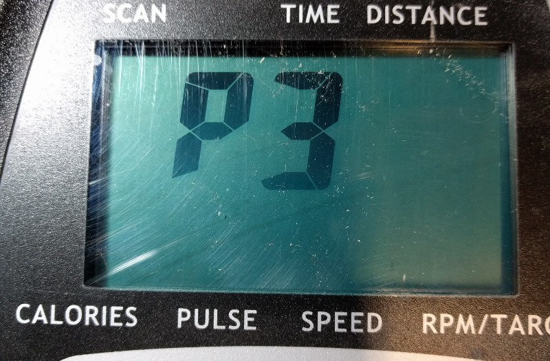
The elliptical trainer is okay. It was also rather difficult to put together. And there's a bug in two of the six training programs that prevents it from displaying how fast you're supposed to be going at any given stage. Obviously a discerning shopper would have take this back. But I did okay.
The Problem:
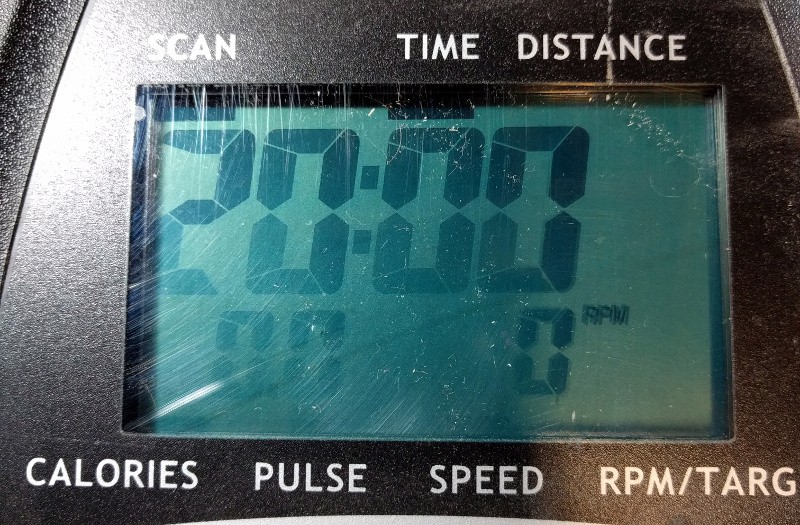
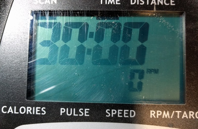
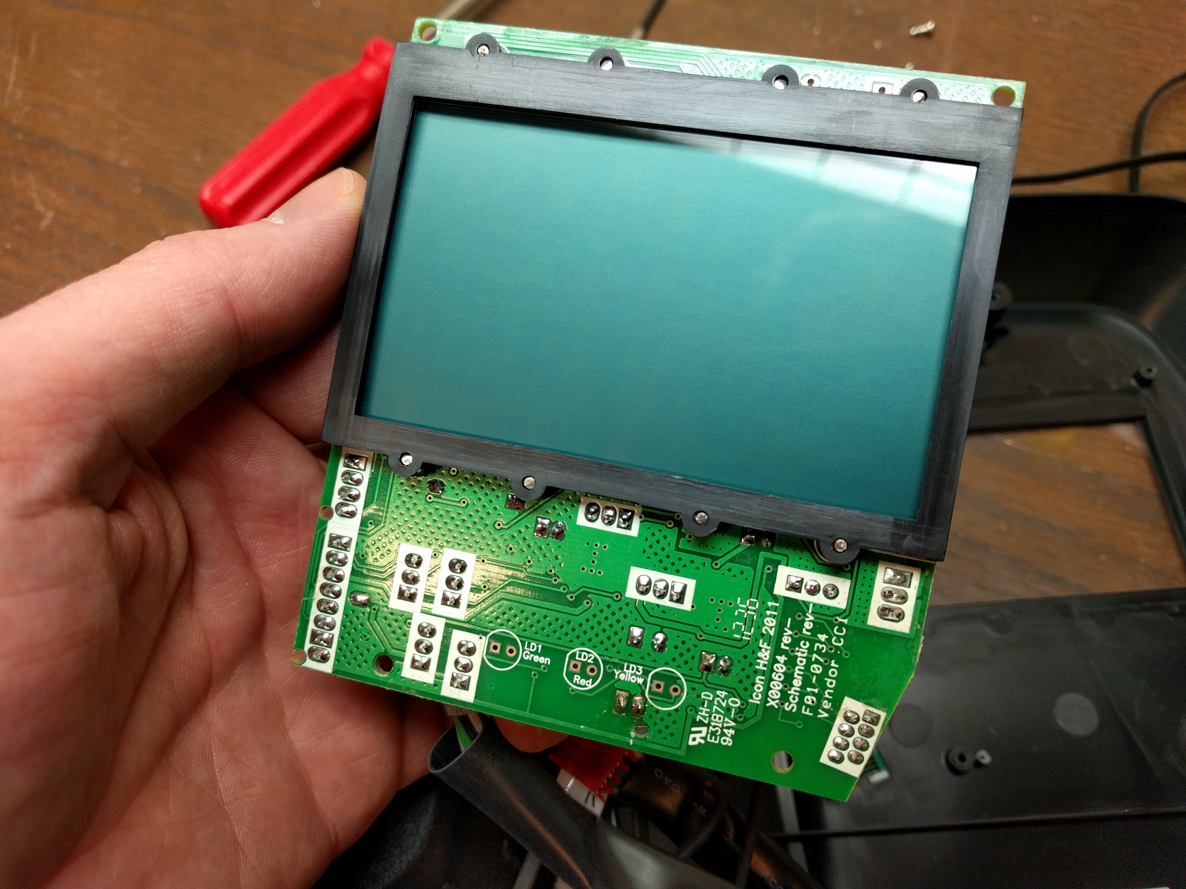
For me, the viewing angle and contrast of the non-backlit LCD display is pretty awful. The display is about waist height for me. And the optimum viewing angle is about navel height for me. All I really want is some nice bright LEDs at eye-level that tell me my current RPM rate (as a bar graph) and the target rate for the exercise routine I'm working on. I can do this!
First External Display Prototype:
Progress:
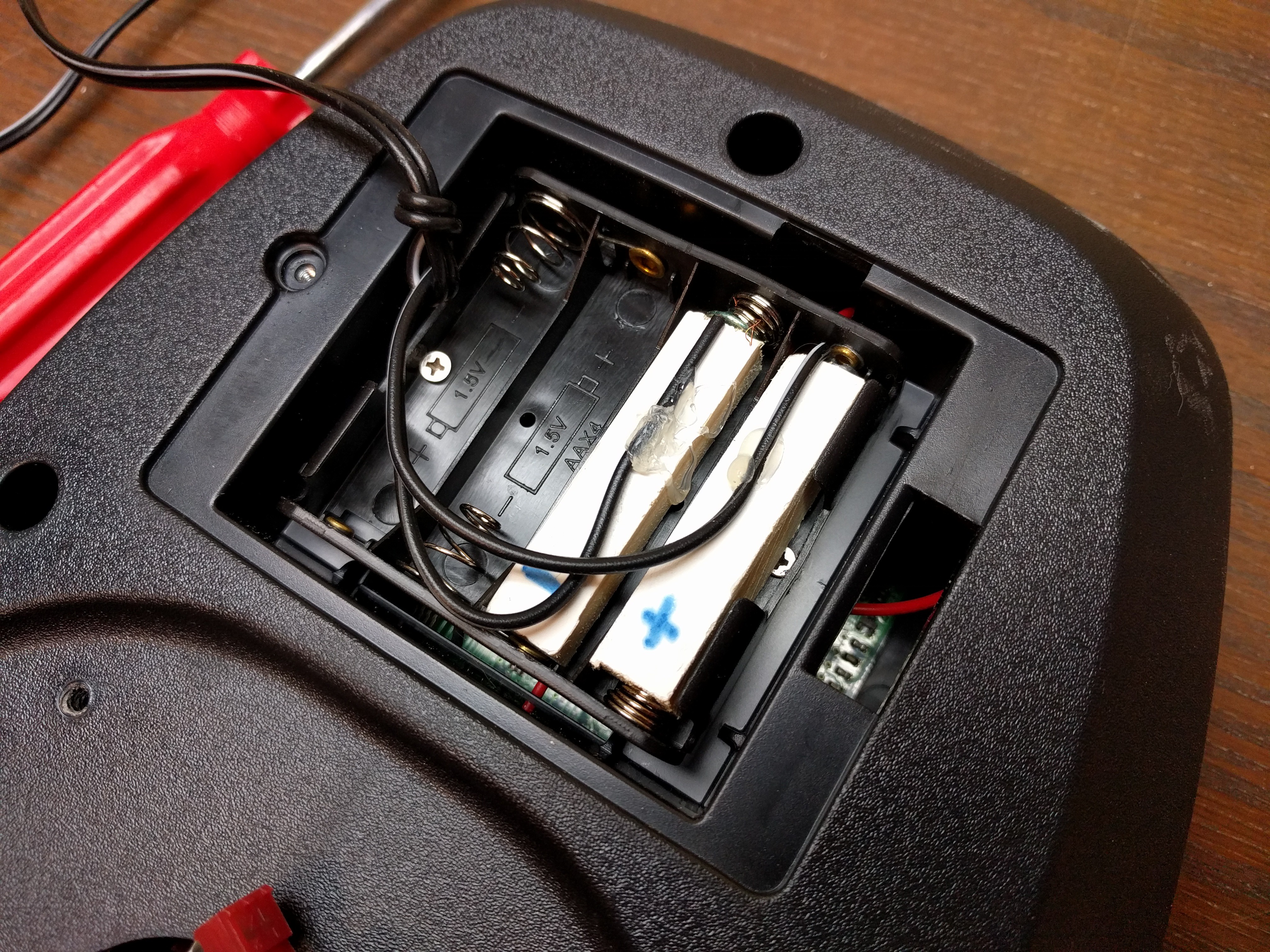
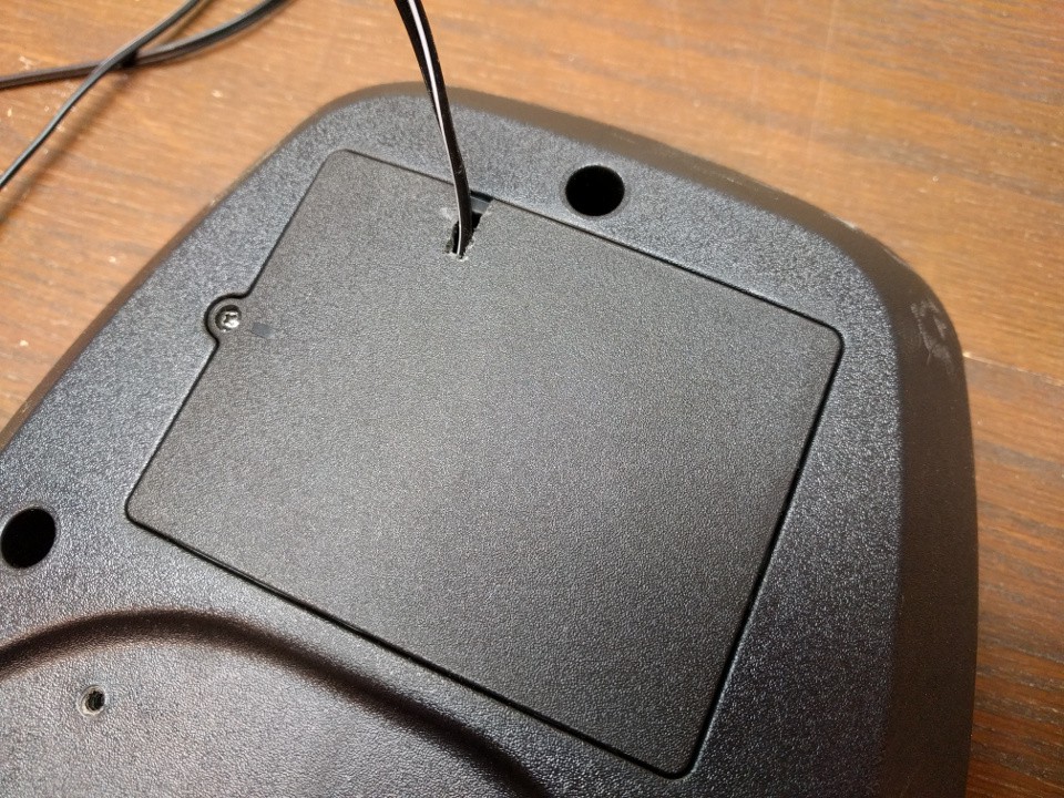
- Stop Using Batteries (read the project log): This is made for 4 AA batteries with no way to power it from mains (facepalm). It's not like this is a portable piece of equipment. After going through one set of batteries I hit my junk bin and made a mains adapter for it.
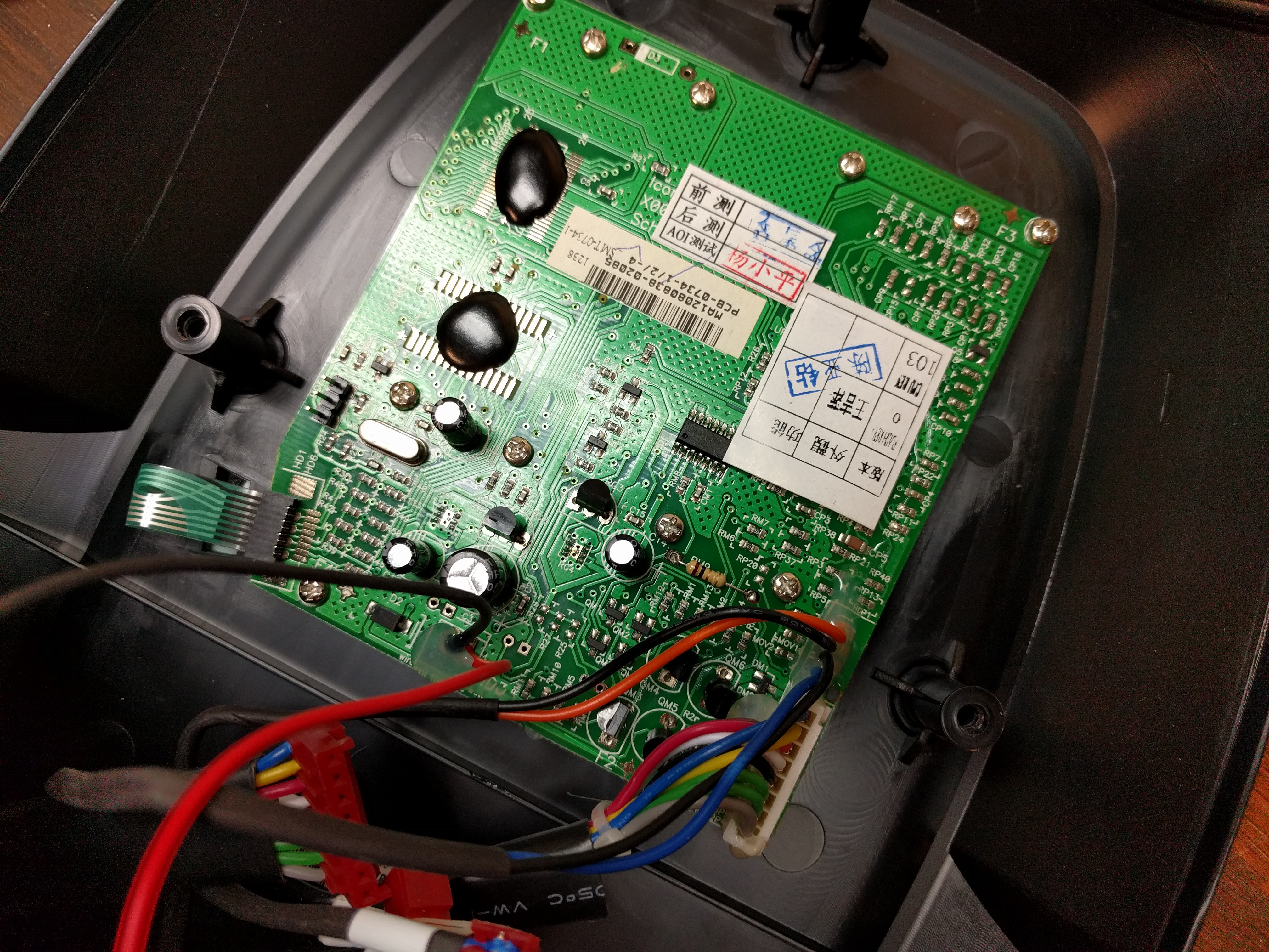
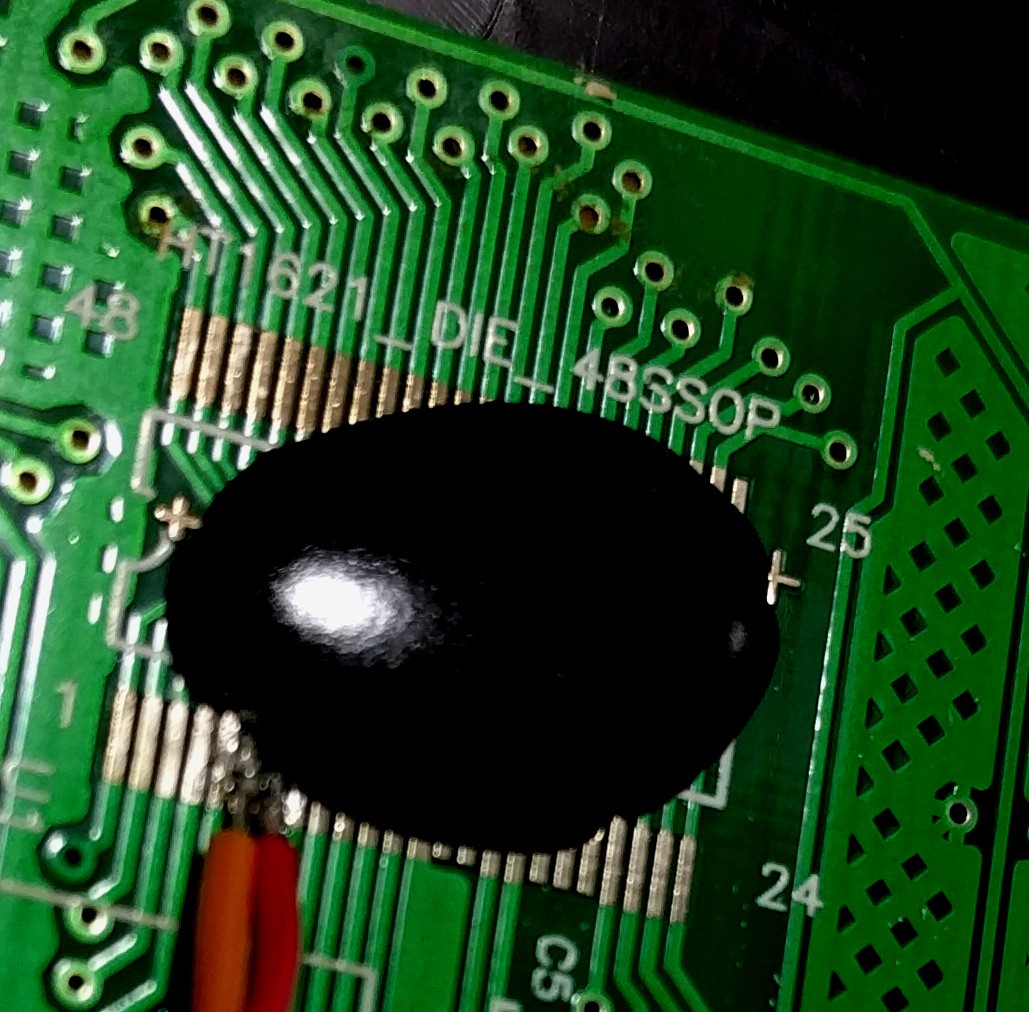
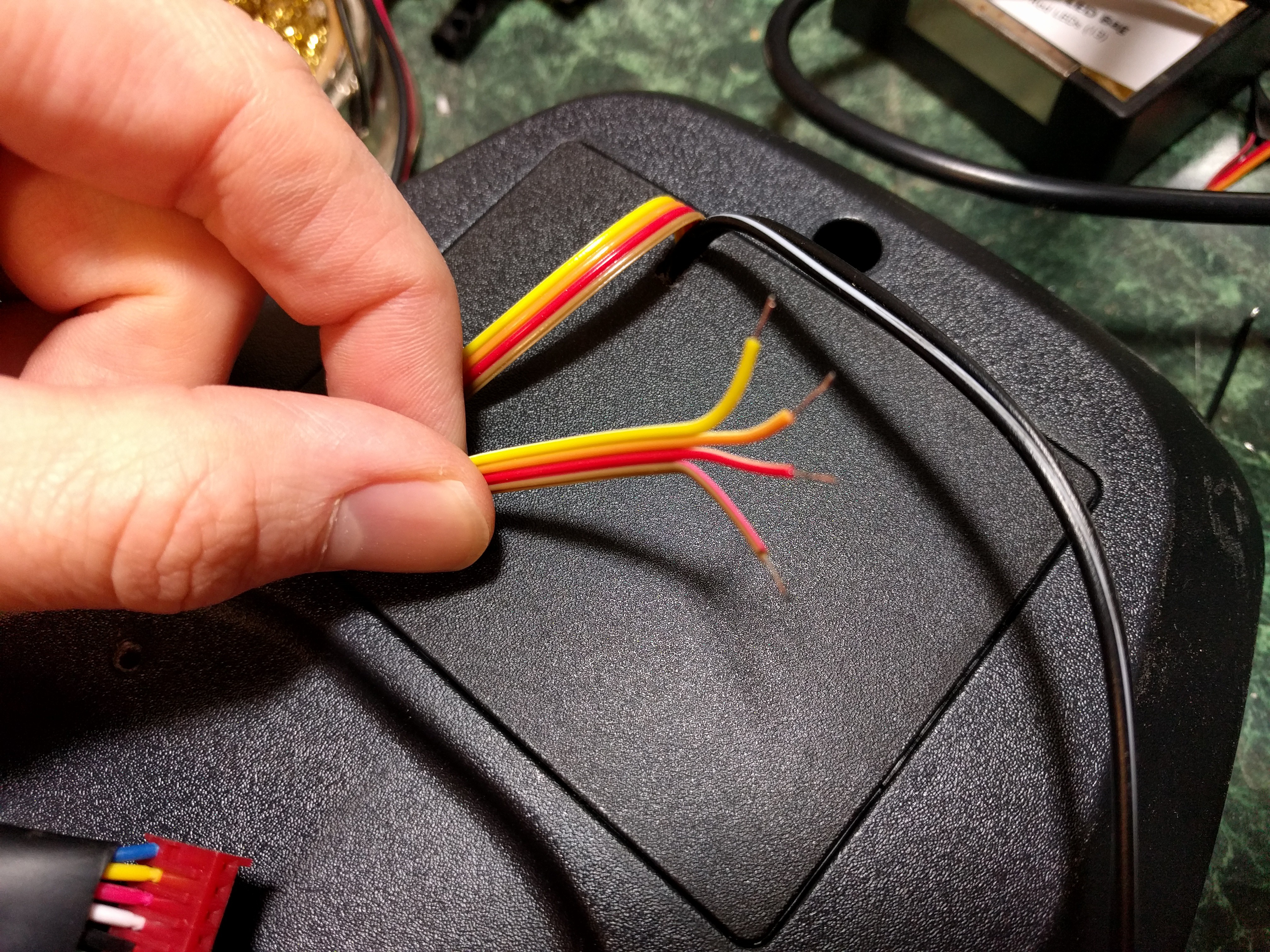
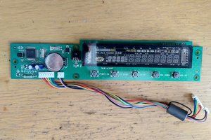
- Investigation (read the project log): I disassembled the controller enclosure and poked around on the board for clues about how it works. Great news, there's a separate LCD controller potted under some epoxy but they wrote the chip number on the silk screen!
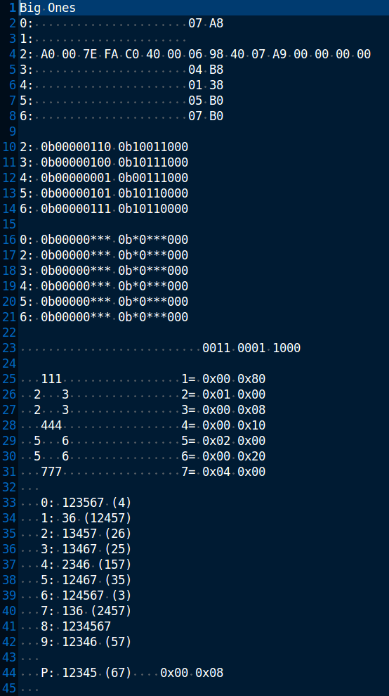
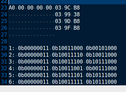
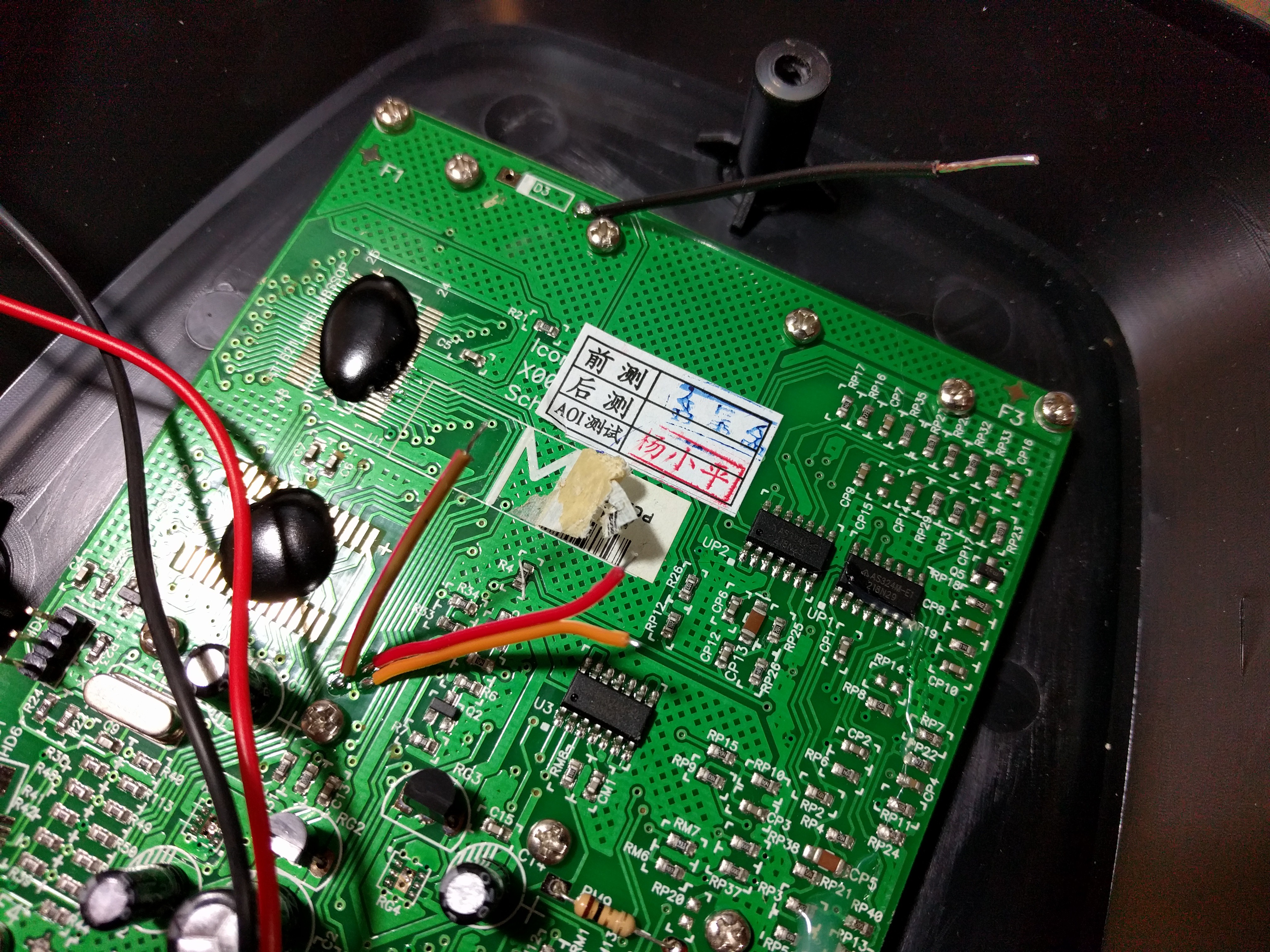
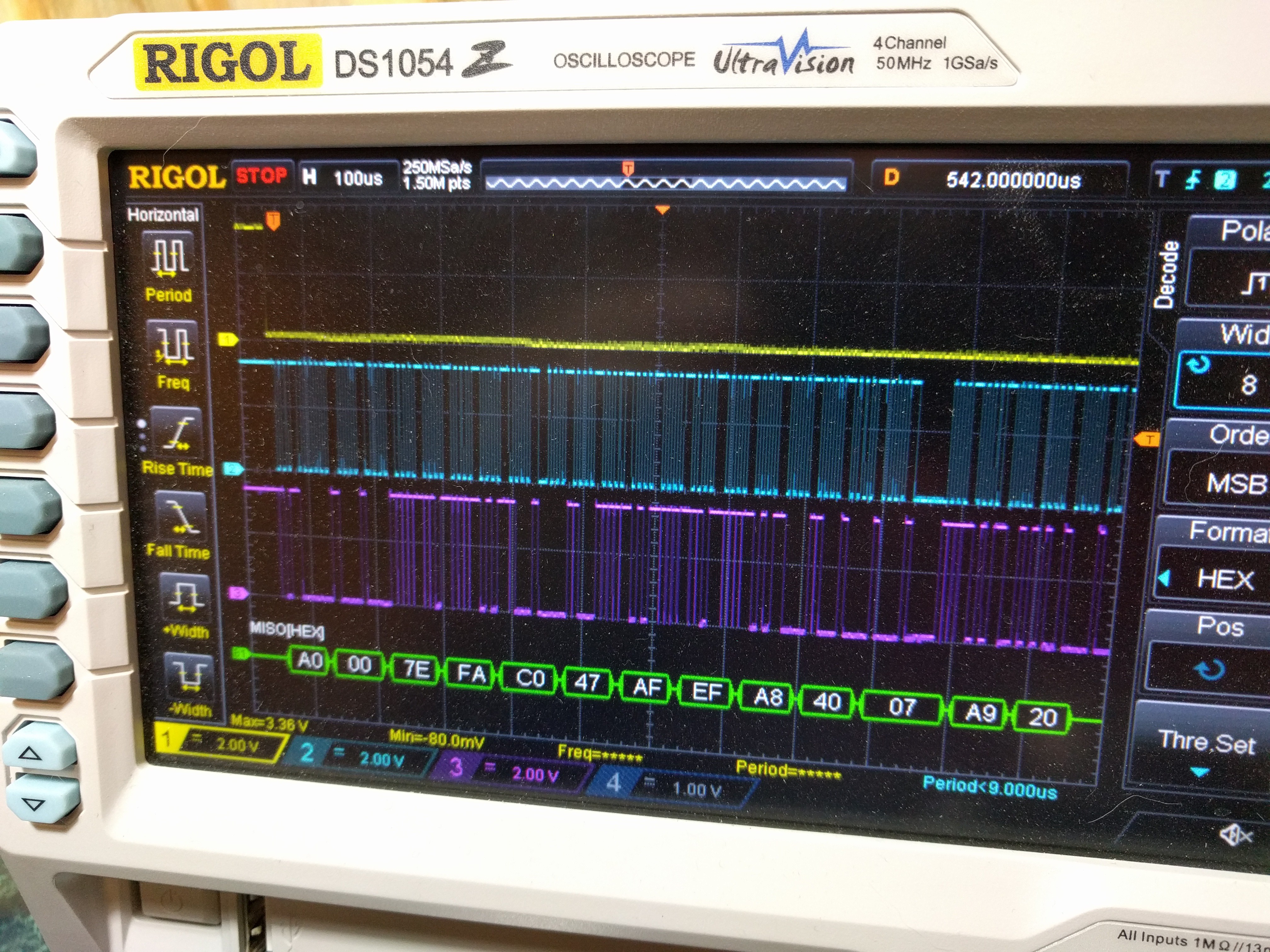
- Reverse Engineering the Protocol (early samples and how I figured it out): All I want to do is make a second display that sniffs the SPI commands on the stock controller and acts accordingly. I've been sampling data and working out the scheme.
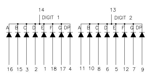
- Prototype Hardware (read the project log): Implemented a proof of concept using ATmega168 and a two-digit 7-segment display that receives LCD data from the elliptical machine, decodes it, and shows the middle two digits of the time display on the breadboard's LED display.

 Spotting the Peculiar:
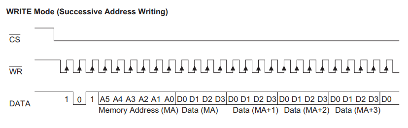 Look at the data line and count the bits up to the first data nibble. There are 3 bits to signify a "write" operation, then 6 bits for the memory address followed by an indeterminate number of 4-bit nibbles of data.
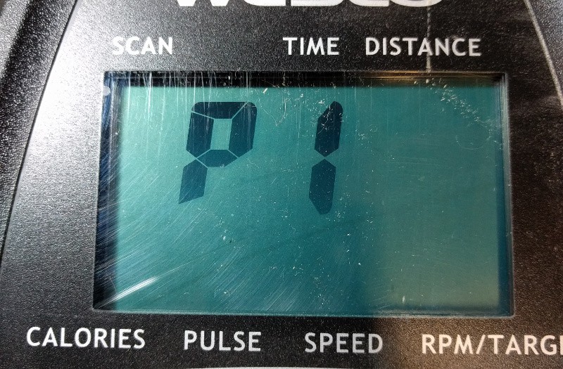
 Lauri Pirttiaho
 Jarrod
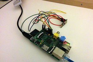
 surfingsteve
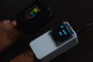
 NextPCB