 Mike Szczys
It was easy to take the computer off of the elliptical machine. All the screws are standard phillips... four holding it to the metal bracket on the machine, five holding the two pieces of the plastic enclosure together.
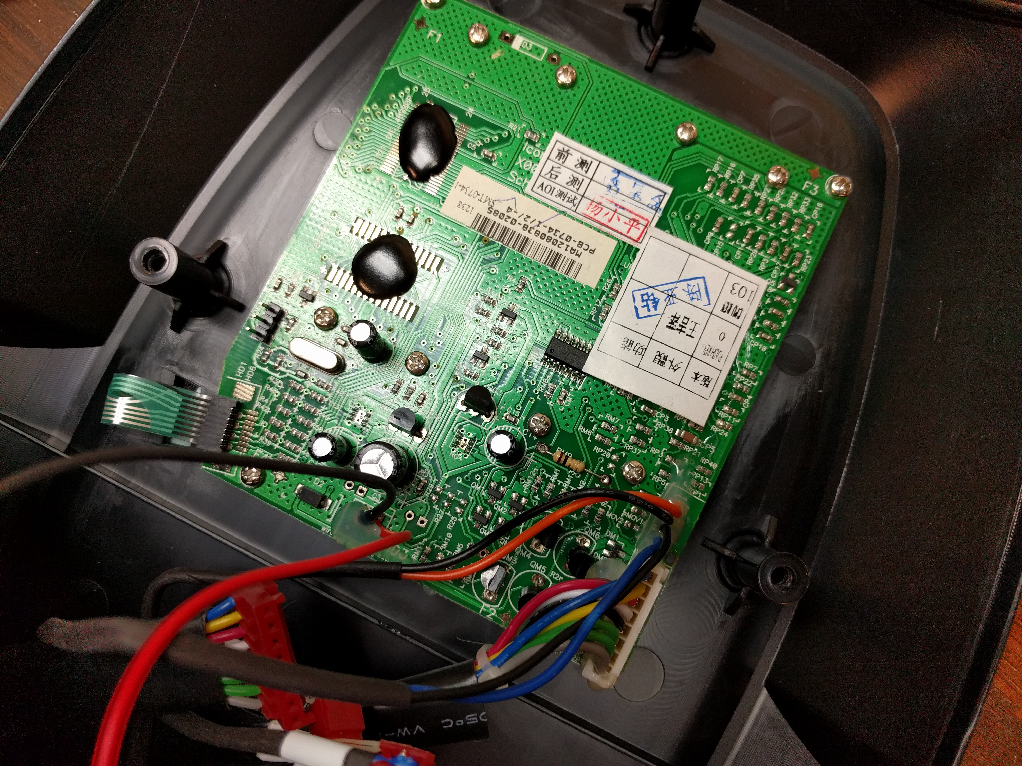
Back of the single-PCB computer. Just remove four silver screws at the corners to free it. I was thinking it was too bad that the ICs are potted and I wouldn't be able to read part numbers. But there was a pleasant surpise waiting.
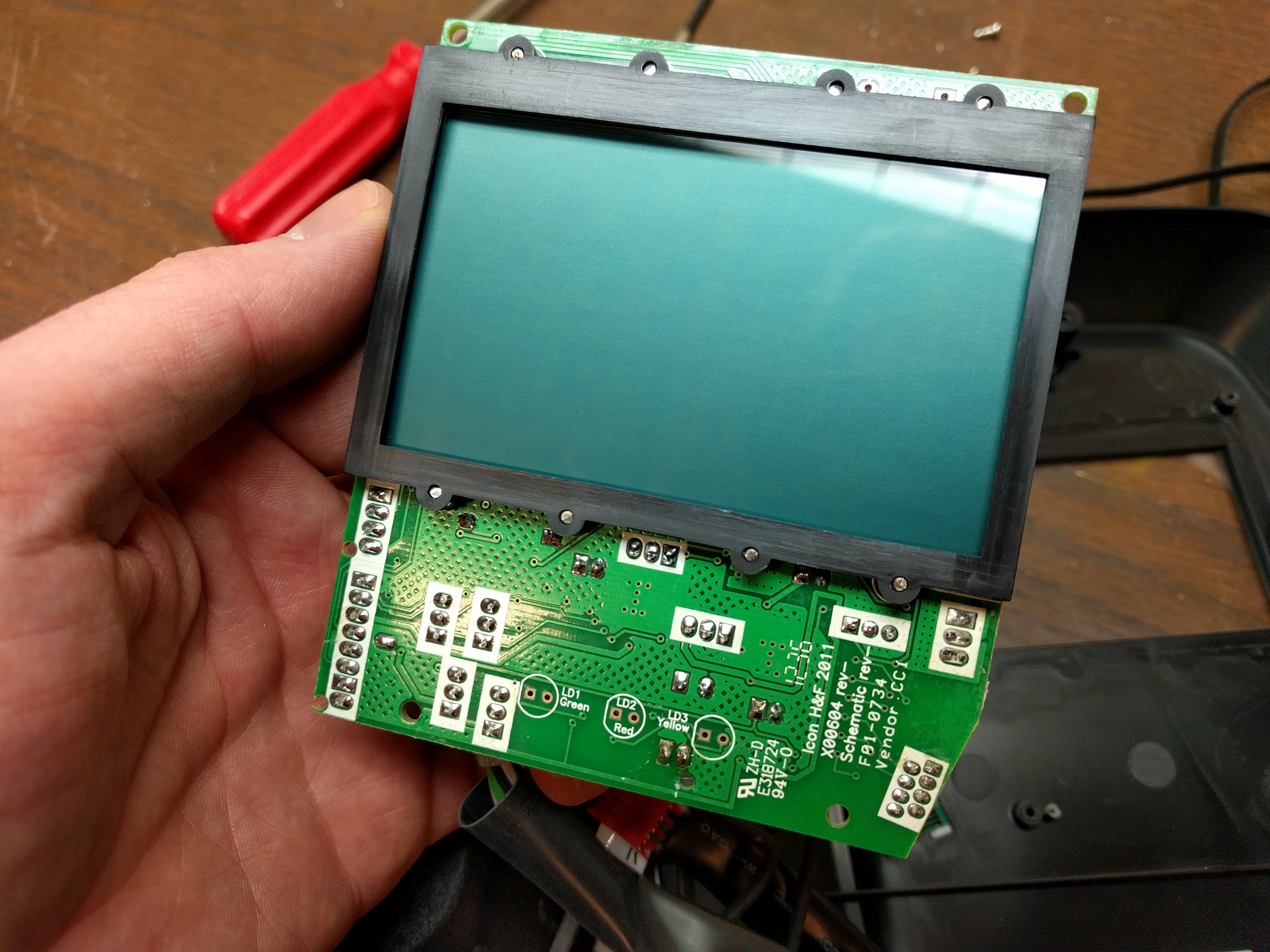
Here's the other side of that board that hosts the LCD. This is a custom LCD so I figured the driver should be pretty simple to figure out as it's just driving a limited number of segments.
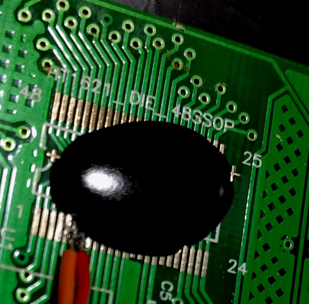
Not a great picture (and ignore those wires... I soldered to the wrong pins but realized it before anything went awry). But what this does show is the very conveniently named component. The silk screen reads "HT1621_DIE_48SSOP". There's a datasheet for that and it lets you know the pins we're interested: CS, WR, and DATA. I traced those out and soldered wires onto via that made the task pretty easy.
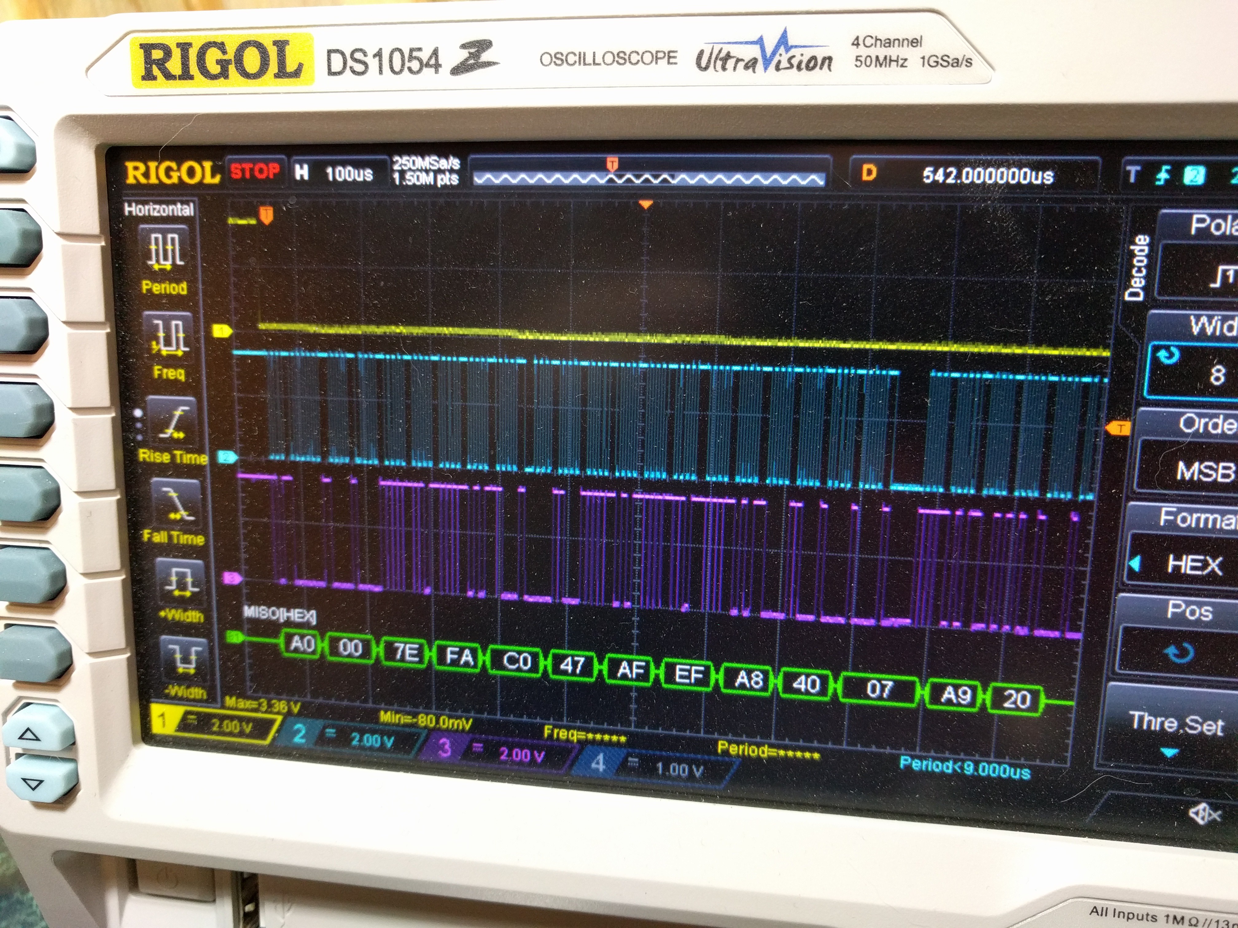
I've never used the SPI decode feature of my RIGOL 1054z before so I thought I'd give it a try. Success! I took a few sample readings and saved them to CSV on a thumb drive to start the investigation. I don't have a logic analyzer but my Bus Pirate is also a viable option for figuring out the LCD data I want to sniff.
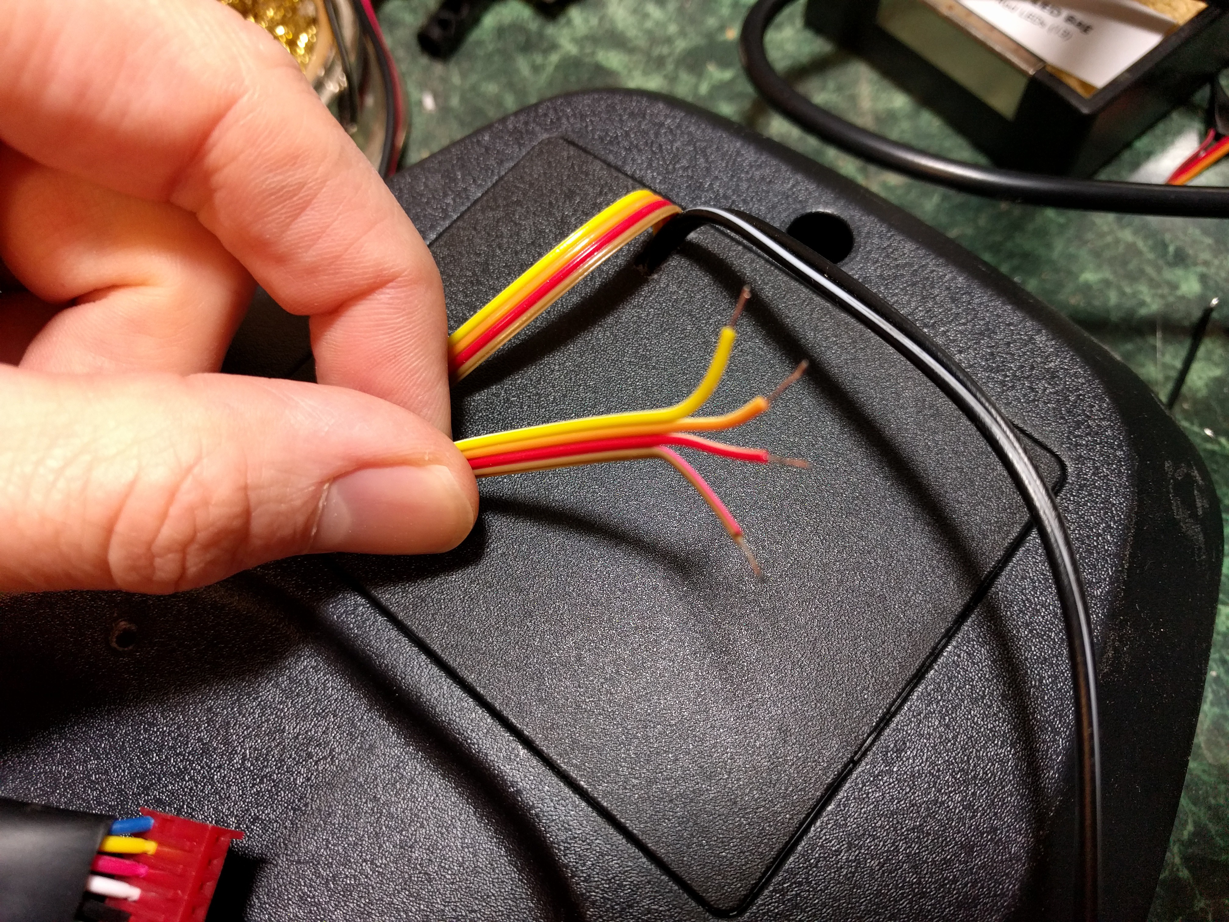
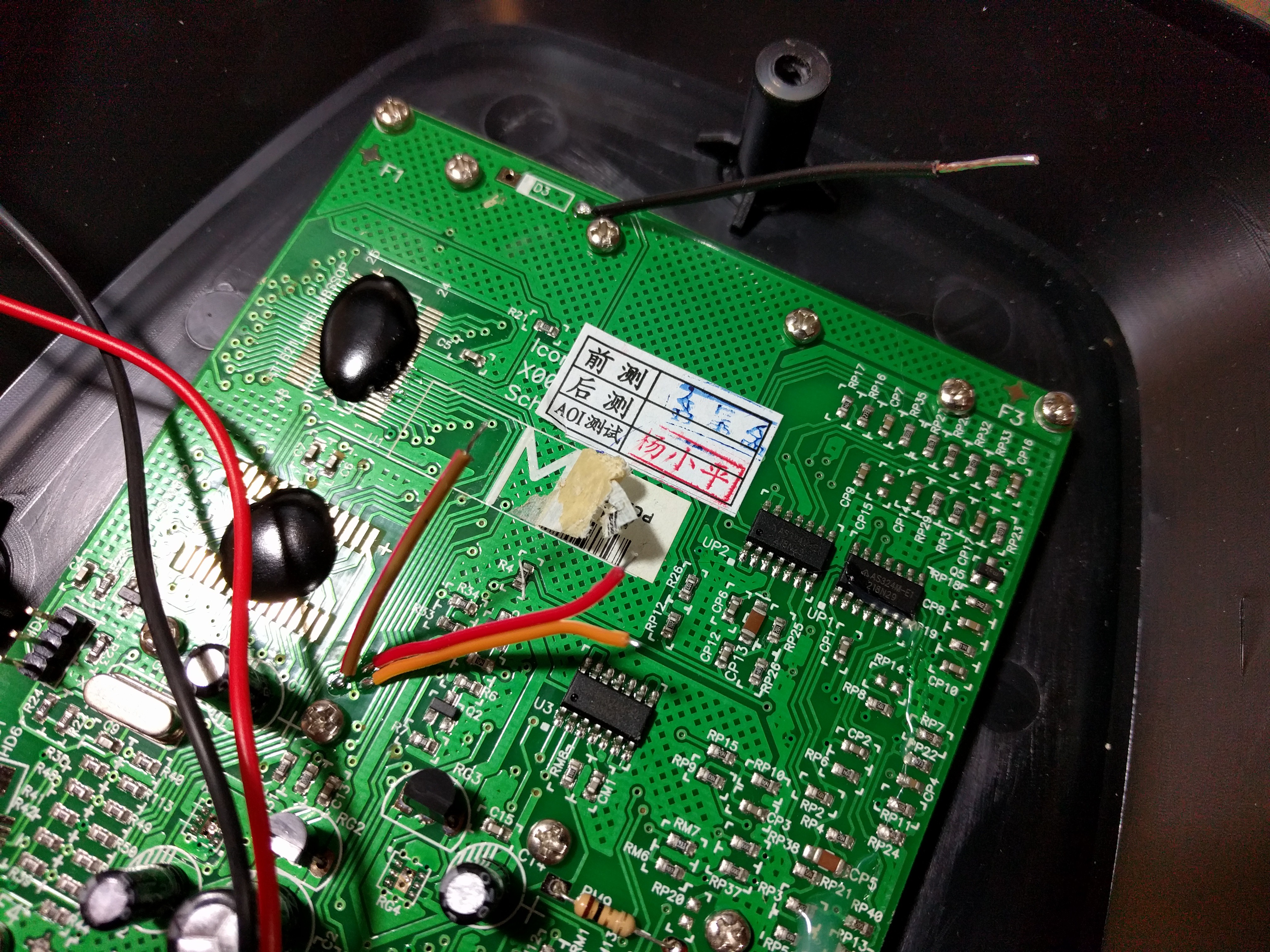
I actually use this thing exercise so I wanted to get it back together asap. Now that I knew my test points were valid I soldered on some ribbon cable, snaked it out the battery door, and put everything back together.
It still works, yay! I just need to figure out the order of the serial data and I should have no problem implementing my own auxiliary display that just listens in on the SPI bus.
For my own records... that ribbon cable is as follows:
- Brown: Ground
- Red: CS
- Orange: WR (CLK)
- Yellow: DATA
Discussions
Become a Hackaday.io Member
Create an account to leave a comment. Already have an account? Log In.