 Ted Yapo
Here's a first sketch for the digital parts of the design (a pdf version can be downloaded here).
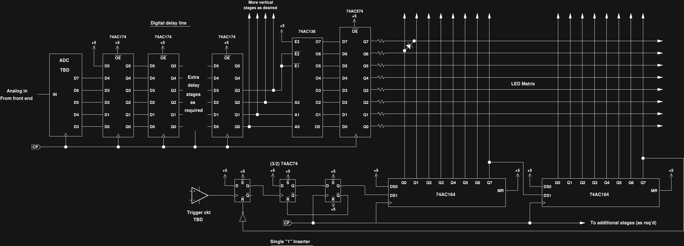
The horizontal sweep is done with a series of 74AC164 8-bit shift registers, so the horizontal resolution can be expanded in multiples of 8 columns (you can also use less than 8 columns on the last register). This method is faster and easier than a decoded counter, but requires that a single "1" bit is inserted into the shift register to start each sweep. Three 74AC74 d-flops form the inserter, which starts a single "1" bit rippling through the columns when the trigger input goes high. No retriggering is allowed until the "1" exits the shift register.
The vertical driver starts with a flash or pipelined 8-bit ADC. I haven't chosen the exact ADC yet, but the AD9057, and AD9293, and ADS831 are on the list to consider. The lowest few bits out of the ADC are discarded, and the most significant four or five bits (depending on the chosen vertical resolution, TBD) enter a delay line made from 74AC174 d-flops. This delay line keeps the trigger point on the display, as opposed to being off the left edge - in classic Tek scopes, an analog delay line served the same purpose. In this case, it centers the trigger point, but doesn't let you adjust the horizontal position - which is fine with me. Depending on the display size and the amount of pipelining inside the ADC, a different number of delay stages will be required.
The output of the delay line is decoded into a 1-of-N active-low output by a number of 74AC138 decoders (added as required for the number of display rows desired). The 74AC138 allows up to 32 outputs to be decoded (4 ICs) without additional logic. These decoders feature active low outputs, which make the row lines the LED cathodes. A number of 74AC574 d-flops register the outputs of the decoders and drive the LED matrix rows through a set of current-limiting resistors.
The 74AC logic gates will drive 24mA, which should be enough to light high-efficiency LEDs to a decent brightness. Even though the LED matrix will be large, only a single LED in each row and each column is lit in any "frame", so I'm guessing the brightness will be OK.
I'm thinking of prototyping a 1D version that just shows a digital signal on a line of LEDs to test the horizontal sweep circuit.
I'm still thinking about the timebase. DDS is easy, but getting one that goes up to 80 MHz may be expensive. A 100 MHz oscillator with a chain of divide-by-2 and divide-by-5 counters would make a decent 1-2-5 timebase, although with a lot of components.
I'm also still thinking about the analog front end and trigger circuit. I might start with a 50-ohm front end for simplicity, then add a high-impedance buffer of some sort.
Discussions
Become a Hackaday.io Member
Create an account to leave a comment. Already have an account? Log In.
Hey Ted, man oh man, this is certainly more sophisticated than the one I encountered 20 years ago, as the gentleman above stated. I just downloaded the PDF file, and will seriously consider building this :)
Are you sure? yes | no
Check it carefully, you'll probably find bugs I haven't seen yet - it's just on paper so far, but I think the basic idea is sound. I'll post an update once it's built, tested, and working.
Are you sure? yes | no
I'm going to build it still, a nice break from my project...it'll keep me frosty :)
Are you sure? yes | no
Just curious, what software did you use to draw the schematics?
By the way, when I was 10 or so, I found similar oscilloscope design in 80's electronics magazine, it caught my eye, since I could only dream of having oscilloscope at he age. Though, budget of 100 LEDs and few ICs was out of my reach too. The idea of building this recurred all my youth (until I got proper scope), but I always dismissed it. I love to see this project, I wonder how it ends up.
Are you sure? yes | no
I use xfig
https://en.wikipedia.org/wiki/Xfig
if I had known about it, and had access to a UN*X machine back then, I could have drawn the schematic for my original implementation with it. If you like old-school X apps, and have used it for say 20 years now, you kind of get used to how it works. I've had a note on my desk to try using dia or ipe instead, which are newer by a decade or two, but at this point, anything else feels like writing with my non-dominant hand (like Eagle vs KiCAD or LTspice vs anything).
There are a bunch of builds from those days documented on the web now; unfortunately mine didn't survive. I think it had almost the perfect combination to inspire back then - LEDs and oscilloscopes - two fascinating devices.
Are you sure? yes | no