 Ted Yapo
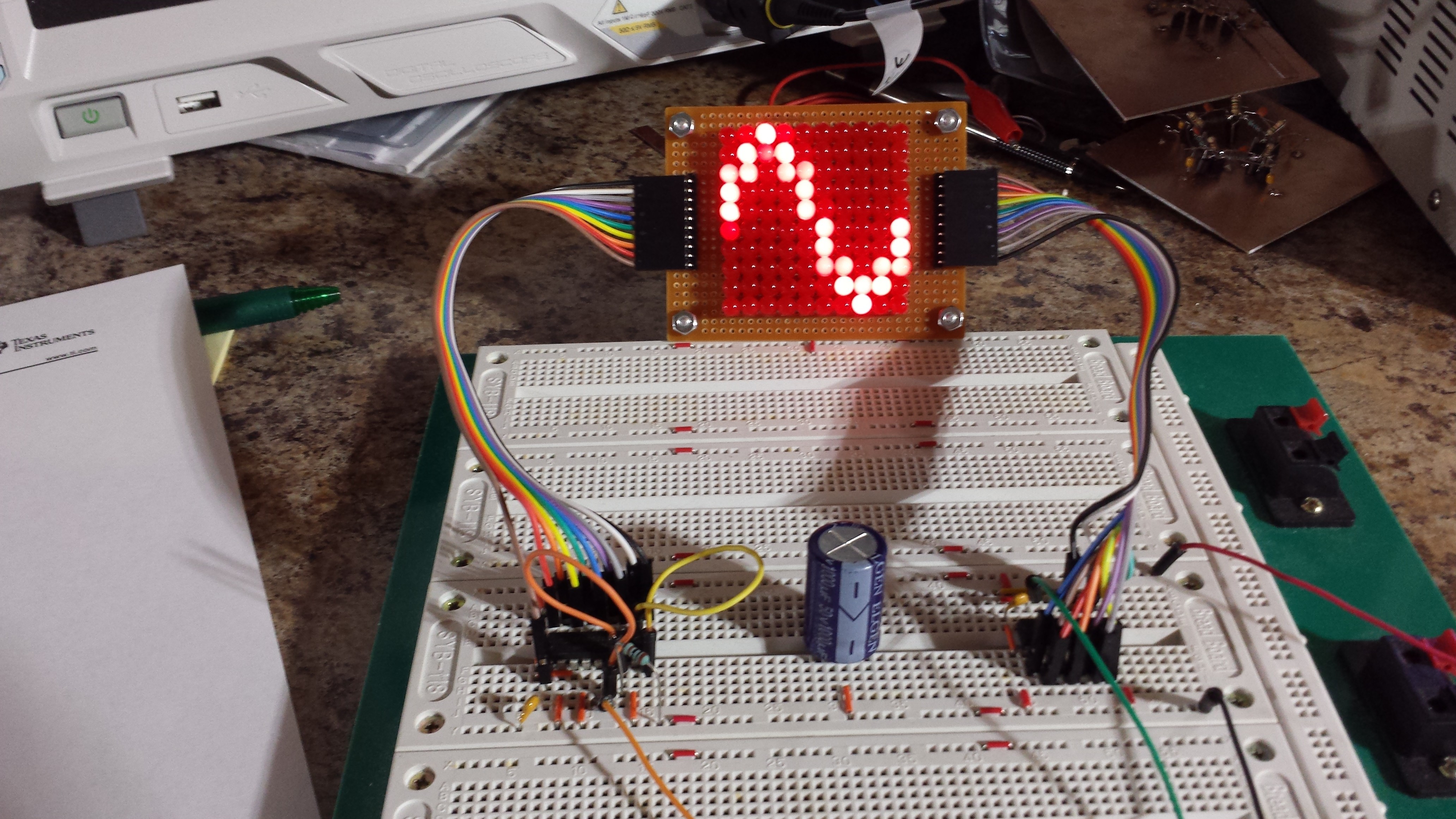
I saw an email notification that my 10x10 0603 LED PCBs are supposed to arrive Monday. This inspired me to make a 10x10 with 5mm LEDs so I didn't have to wait. Some parts were just as much of a pain as when I first did it 30+ years ago.
One of the issues was the little lip at the bottom of the LEDs - this keeps them from packing closely together. I know you can get LEDs without the lip, but I used what I had at around midnight last night. Just as I had done before, I ended up filing this lip off each LED, which took most of the time. The soldering fun more than made up for this inconvenience.
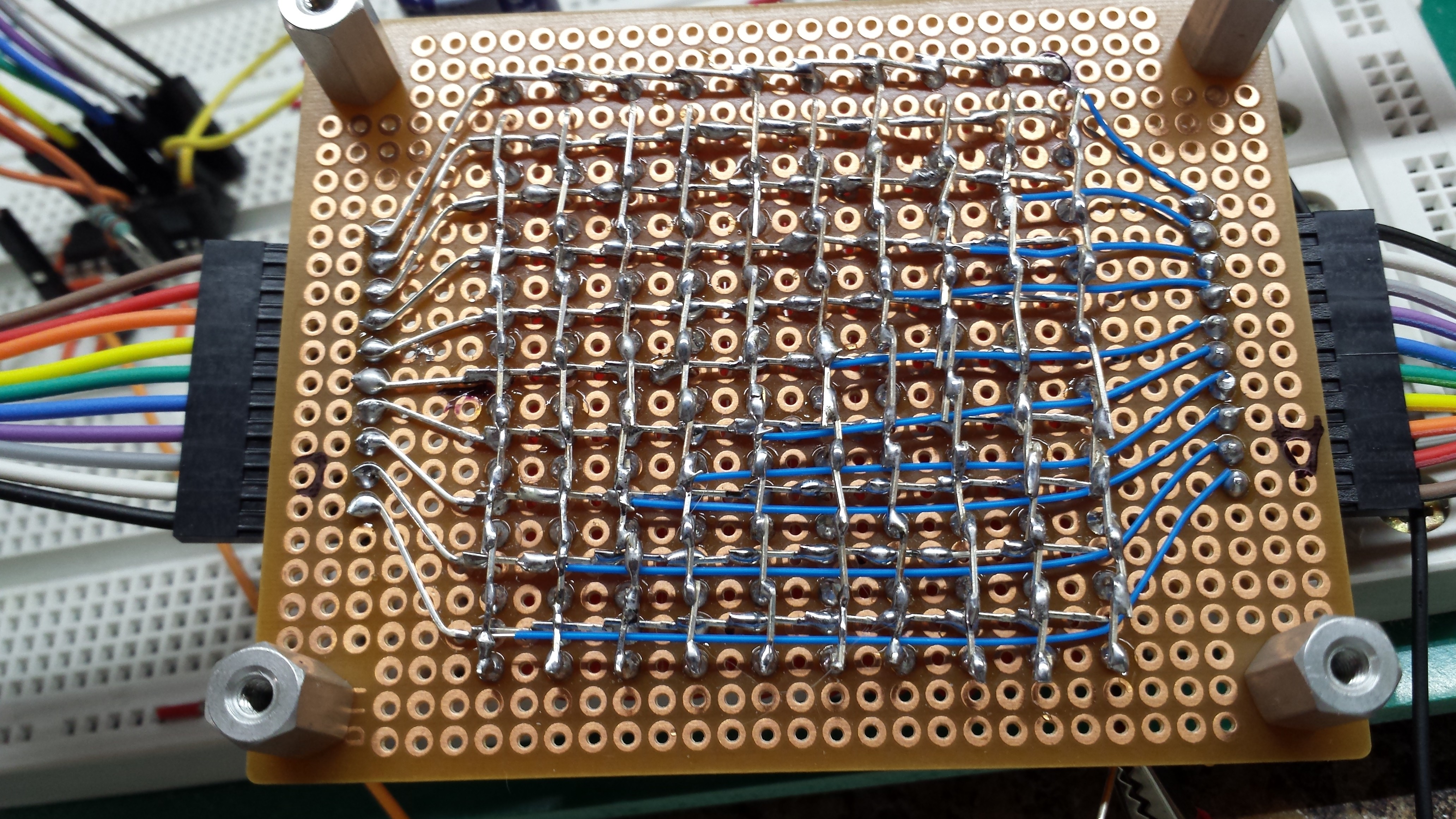
The matrix is connected underneath, with the connectors brought out to 0.1" headers, like on the PCBs:
After assembling and testing the board, I've determined that I have about a 1% error rate in inserting LEDs correctly. One of them got soldered in backwards, and I had to unsolder the neighbors to replace it. Not too bad, I guess considering it was a late-night adventure.
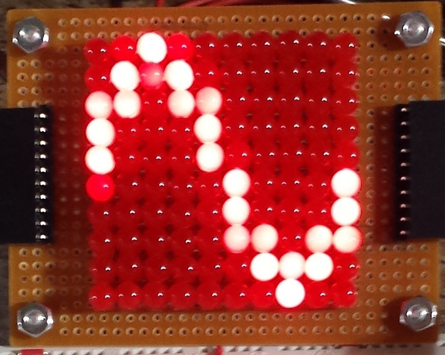
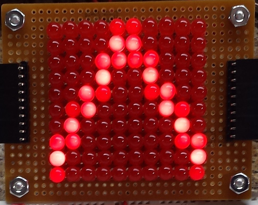
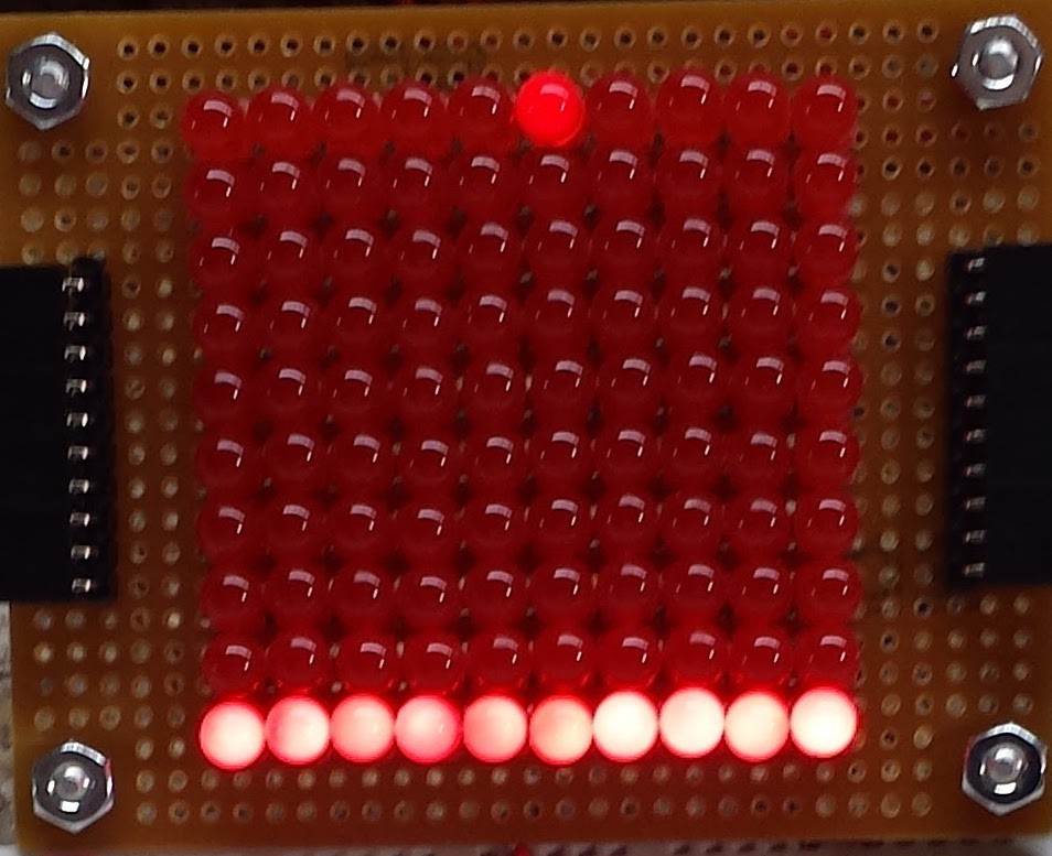
The test driver uses an LM3914 to drive the vertical and a 74HC4017 to drive the horizontal sweep. Using a dual-channel DDS to drive both makes testing a breeze. With the horizontal set to 10x the vertical frequency, the display is rock-stable, since the DDS outputs have a constant phase relationship. Here are sine, triangle, square, and pulse waveforms displayed:
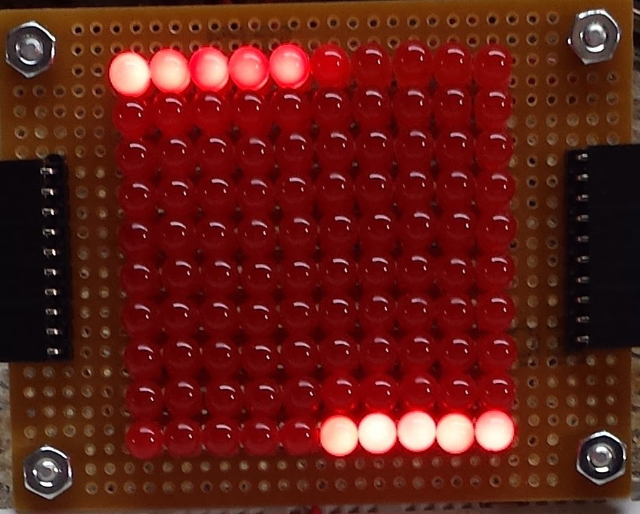
I found that the LM3914 seemed to start skipping LEDs with a sine wave of about 50 kHz or above. I seem to remember them being faster before - although this one was an ebay purchase, and could be a fake, I guess. For audio frequencies, this seems like it would be fine. I'd like to go 1000 times faster :-)
The display is about how I remember it - due to the low resolution, a slowly-scrolling display seems easier to visualize than a steadily-triggered one. By setting slightly different frequencies at the DDS outputs, crawling displays can be made, too. Here are the same waveforms in motion:
Comparing this to the build from my teens, I have to admit, some of the magic is gone. I still remember the first waveform I saw on the thing - it was 60Hz power-line hum. I left the thing on overnight like a night-light with that slowly-crawling sine on it.
As with most things, the cure here may simply be MORE LEDs...
Discussions
Become a Hackaday.io Member
Create an account to leave a comment. Already have an account? Log In.
I never did finish the one I was building, also as a teenager. I gotta say, seeing yours functioning, it looks a lot more interesting than I imagined, even as a kid. Definitely more LEDs wouldn't hurt, but surprisingly interesting with only 10x10.
The dilemma, as I recall, with the one I was building was a flawed understanding of what 4017-cascading meant, but it just occurred to me that maybe a shift-register after one 4017 would do the job. Got some datasheets to peruse.
For the blinky-lovers out there, triple-trace with RGBs? :)
Are you sure? yes | no
I like the RGB idea - that would have even worked when they were only RG. I remember such things even back then - three-legged LEDs with red and green inside - perfect for dual trace - but couldn't have imagined 100 of them in a single project. 100 red LEDs cost me $13 in the mid-1980s, which I thought was a bargain, since they were a few bucks each at that place - you know the one. I got the current set of 100 for $1.95. They're the same low-brightness lousy red indicator LEDs.
I think the straightforward cascading of 4017s gives you another decade - counting tens instead of 11-20. I'm pretty sure you can make a modulo-18 counter by sacrificing the last output of the first 4017 and the first output of the second 4017 to drive the enable and reset lines of the opposite counter. This gives you 18 output lines instead of 20, but doesn't require additional logic. I worked it out once on paper, but have never tested it.
Are you sure? yes | no
I'll have to contemplate the 18-counter.
Yeah, 100 RGBs sounds absurdly expensive to me, but some blinky-lovers sure love their blinkies!
I just saw bi-color (R/G) in surplus the other day and thought "what would I ever do with that many?"
Are you sure? yes | no
@esot.eric Here's one. I think you can do it without the diodes.
http://www.brighthubengineering.com/diy-electronics-devices/87667-build-an-interesting-light-chaser-circuit-by-cascading-4017-ics/#imgn_0
Are you sure? yes | no
@Ted Yapo Good find. Looks *feasible*... But hard to follow without labels... and the miswiring of the LEDs to V+ doesn't help. Something doesn't quite sit right with me on that one... Seems like it'd need a couple *more* diodes, to me.
Are you sure? yes | no
@esot.eric You can't have too many diodes.
Are you sure? yes | no
I feel really compelled to build an RGB version now, thanks @esot.eric :) 100 RGB leds from China are about 4 euros and somehow I don't think that the rest is that expensive, or is it?
Are you sure? yes | no
a 74HC4017 and (3) LM3914's will probably cost less than the LEDs. Timebase and analog front end not included :-)
You need common anode LEDs, since the 74HC4017 has active high outputs, and the LM3914 are active low.
You might also need buffers (MOSFET or BJT followers might work) on the 74HC4017 outputs to be able to source current for the R, G, and B channels.
Are you sure? yes | no
The IOL/IOH spec is a guideline for proper signal levels by the next stage of logic. You can sort of ignore that as long as you stay well below the absolute max.
NXP 74HC4017 (Absolute Maximum Rating): IO output current: +/-25 mA
Modern day LED are very efficient, so usually a couple of mA (average) is good enough. Multiplexed by 10 (1 stage of 4017), then we are only talking about 20mA.
All else fails, then buffer the signals.
Are you sure? yes | no
I also found the 4017 / 3914 combo in my Mims notebook, very inspiring stuff :)
Are you sure? yes | no
I have a fever, and the only cure is more LEDs :) and a full, HD version of the cowbell sketch.
Are you sure? yes | no
three words: soft white underbelly
Are you sure? yes | no