 Ted Yapo
I've been playing with filtering the display for contrast and filling the space between pixels.Here's how the display looks without any covering, with a 0.15" thick bezel, and with the bezel plus a 116 Tough White Diffusion and 26 Light Red filter.
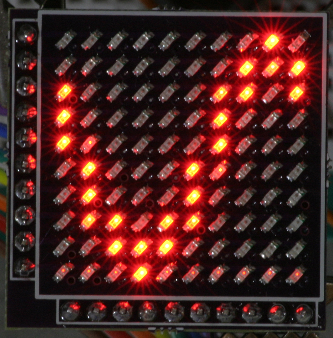
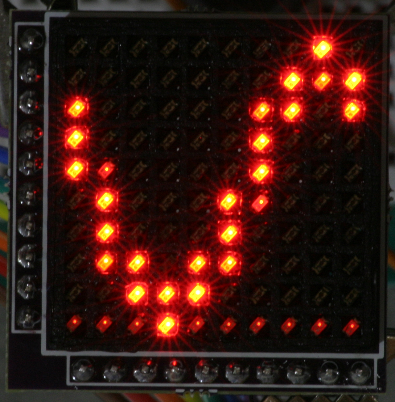
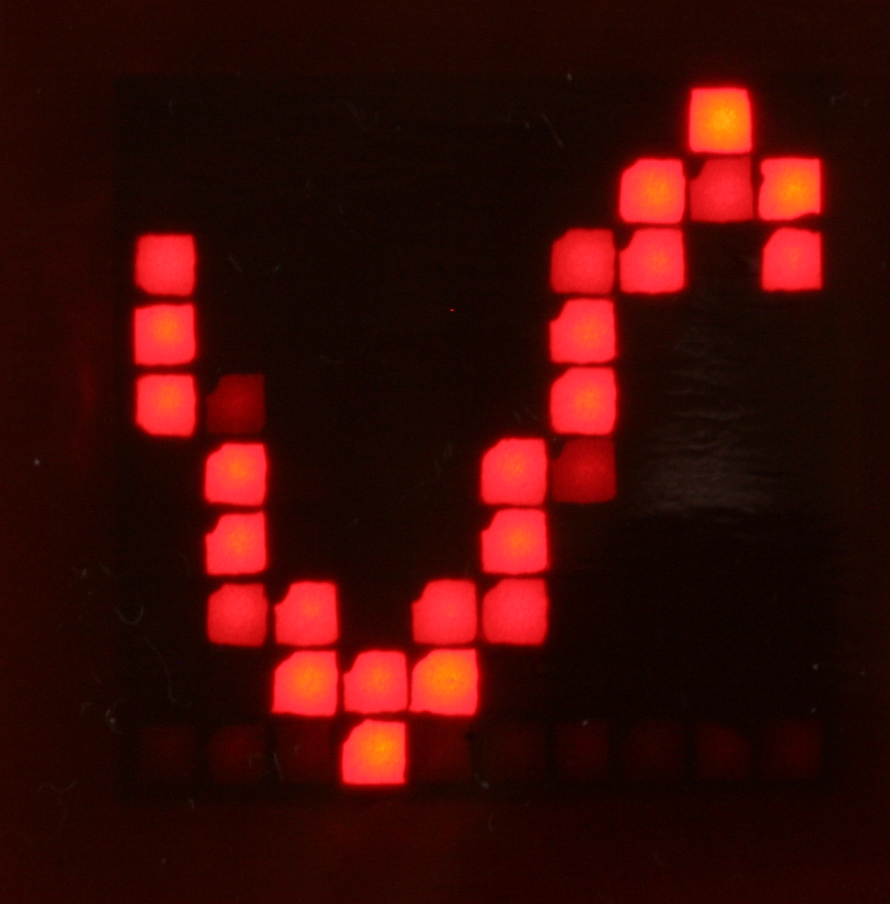
Out of all the many combinations I've tried, I like this last one the best. You lose some light, but the LEDs are really beginning to look like pixels. In the photo, the filters aren't held tightly against the bezel, either, which improves the display a bit. I think the final assembly will need a thin acrylic sheet over the top for protection and to hold the filters flat against the bezel.
I love Roscolux filters - they're made for theatrical and cinematic lighting, but are very useful for general optical hacking. They're relatively inexpensive, come in hundreds of shades, and you can get a free swatchbook full of samples if you go to a theatrical supply store (you might end up having to pay for one online). Once you determine the ones you want, you can order them in big rolls. I found a few dozen useful ones for diffusing and filtering the red LED prototype display in the pack:
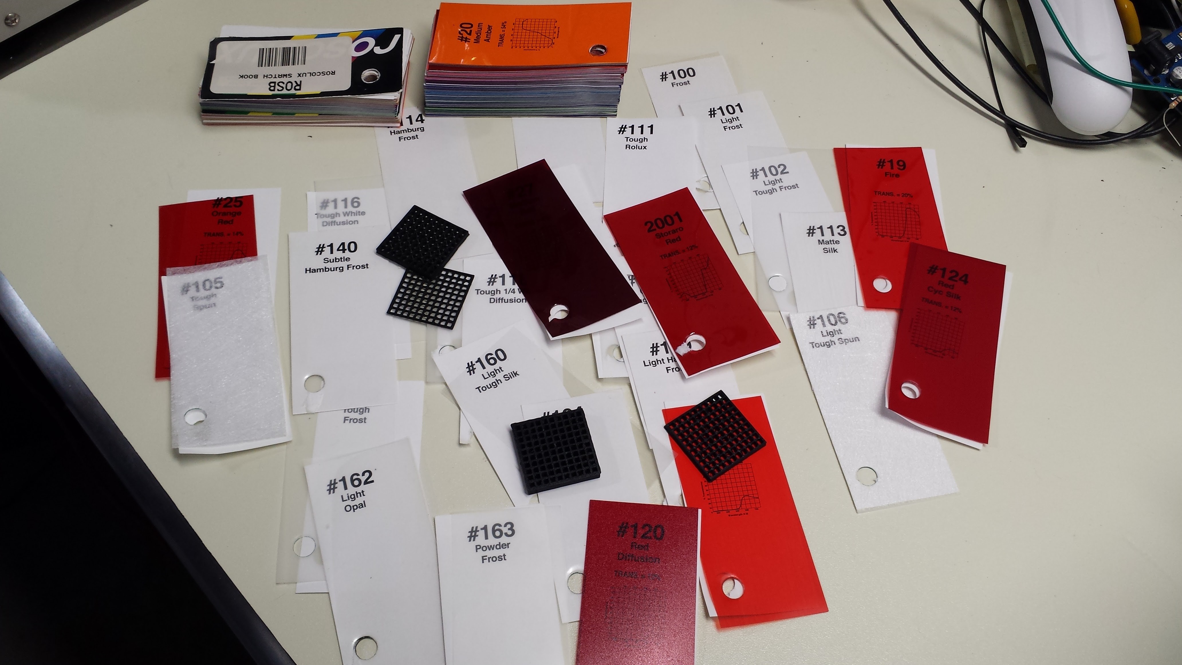
Also shown are the 3D printed bezels with a square hole for each LED.
There are two issues I'm still working on. First, there is a significant amount of light lost. I think I can regain some by adding a white silkscreen covering the PCB, and using a white bezel (currently printed in black). I will try printing the bezel in white, but I wonder if it will allow leakage from neighboring pixels. If all else fails, I'll try painting the black bezel white - that should block light from adjacent LEDs while reflecting more of the center pixel.
The second issue are those annoying dark corners in each pixel cell. Printing this bezel is just at the edge of what's possible with my printing setup - each wall in the grid is only one extrusion wide. Unfortunately, the slicer isn't doing a great job of path planning, and the print head makes a little jog in the corner of each cell. You can see it here in the gray lines:
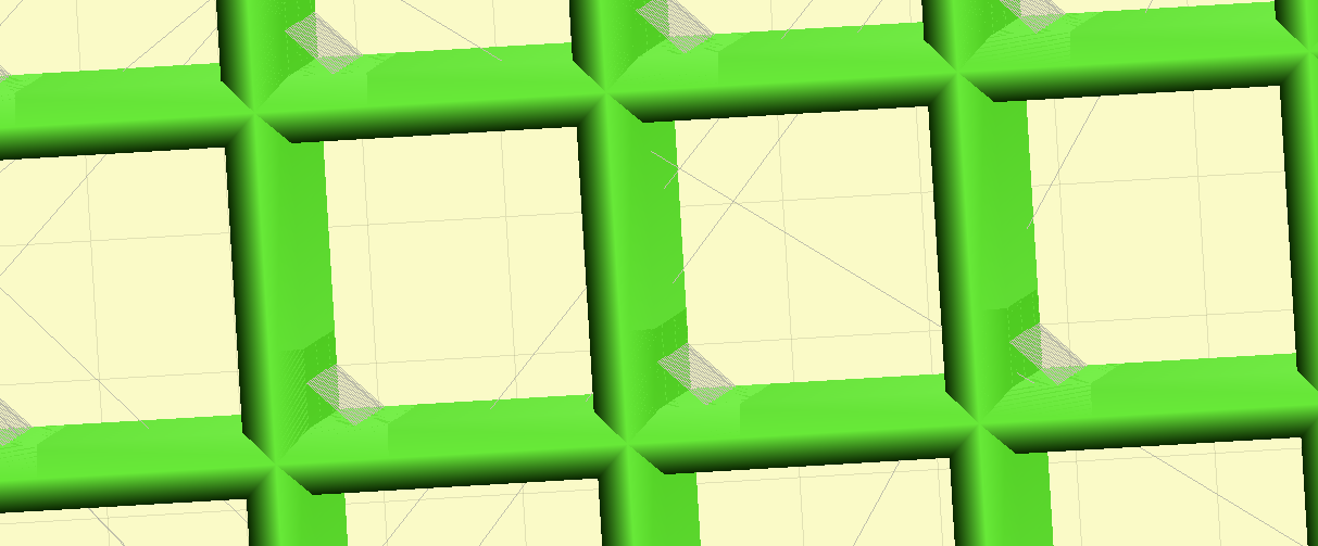
Those gray lines are moves (without extruding material), but the extrusion doesn't stop on a dime, and a little string of filament ends up in those corners - enough to cause those distracting dark corners seen above. You might be able to clear them out with a hobby knife, but I don't think that's practical for larger displays.
I'll play a little more with the printing toolchain, then I might try writing g-code for this bezel directly. I wrote a package a few years ago for 3D printing from Javascript, so I don't think it would be that difficult. For an object like this, the imprecision of triangular modeling and subsequent slicing starts to outweigh the convenience, and custom-written g-code to print the grid might work a lot better. In that case, you have complete control of the path of the print head, and can keep it from making those silly corners.
Another possibility would be to design the grid with semi-octagon cells, which intentionally have four dark corners. It might be that those can be printed consistently. But, I really would like edge-to-edge square pixels...
Discussions
Become a Hackaday.io Member
Create an account to leave a comment. Already have an account? Log In.
Well done, looks great!
Are you sure? yes | no
Noticed the corners right away... but kinda like the look. Maybe not for a 'scope, but groovy nonetheless. The diffusion is excellent.
Are you sure? yes | no
Another random idea - you may try to make bezel out of FR4 material in next PCB order, just like they make internal divisions in carboard boxes
It may be expensive one and thin FR4 would be probably needed, though. Perhaps you can laser-cut the shapes from some cheap material, like vinyl sheets or something. Or even paper.
Are you sure? yes | no
I like the idea, but I'm too clumsy to make this work at the 0603 scale :-(
Laser-cutting gives me an idea, though - maybe I can have a stainless solder-paste stencil cut with perfect square apertures for the top of the display. If the squares were slightly smaller than the worst corner blob, they'd effectively hide the imperfections. Solder stencils are cheap these days, and the eagle ULP layout script could crank one out just as easily as the board itself.
Are you sure? yes | no