 Ted Yapo
While I had an arduino hooked up to the display, I couldn't resist using the ADC to make a software version of the scope. It boasts an ultra-fast sampling rate of 77ksps :-), but is good enough to see how waveforms will look. The result definitely has an analog scope feel - not like the "dead" waveforms on a digital scope at all. I like it a lot.
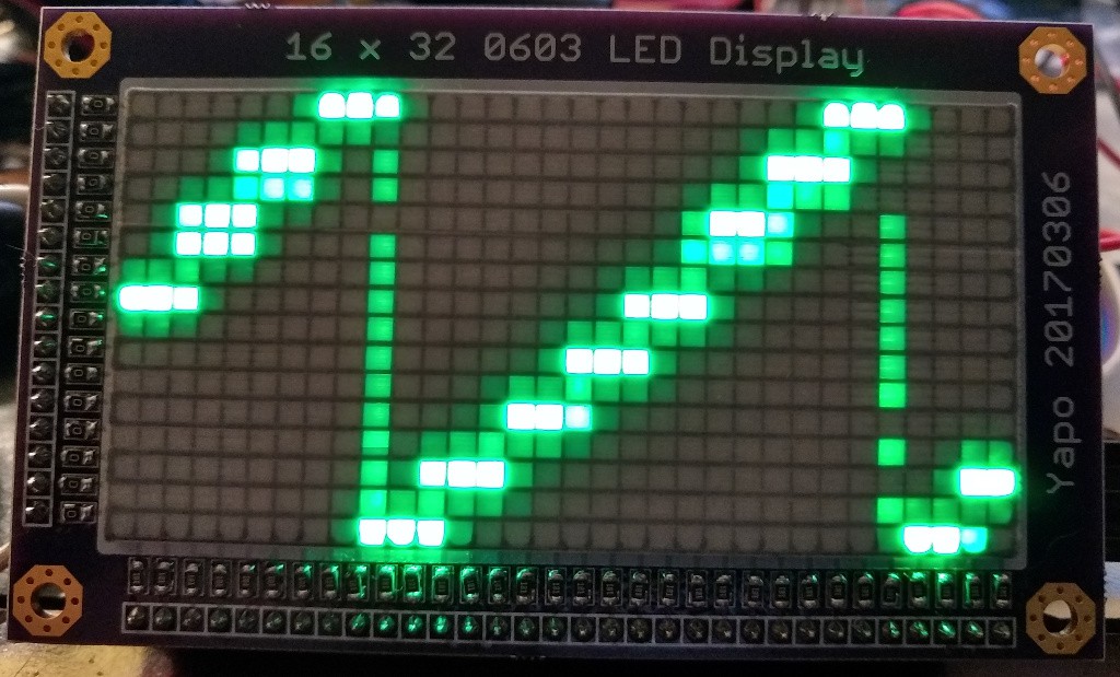
All of the input waveforms were at 3kHz. First up, the staircase. I hooked the output of my DDS to the ADC input pin. This is the default waveform stored in the Arb. memory. Doesn't look that bad. That's not all light bleeding - there's some trigger jitter involved, too - more about that below.
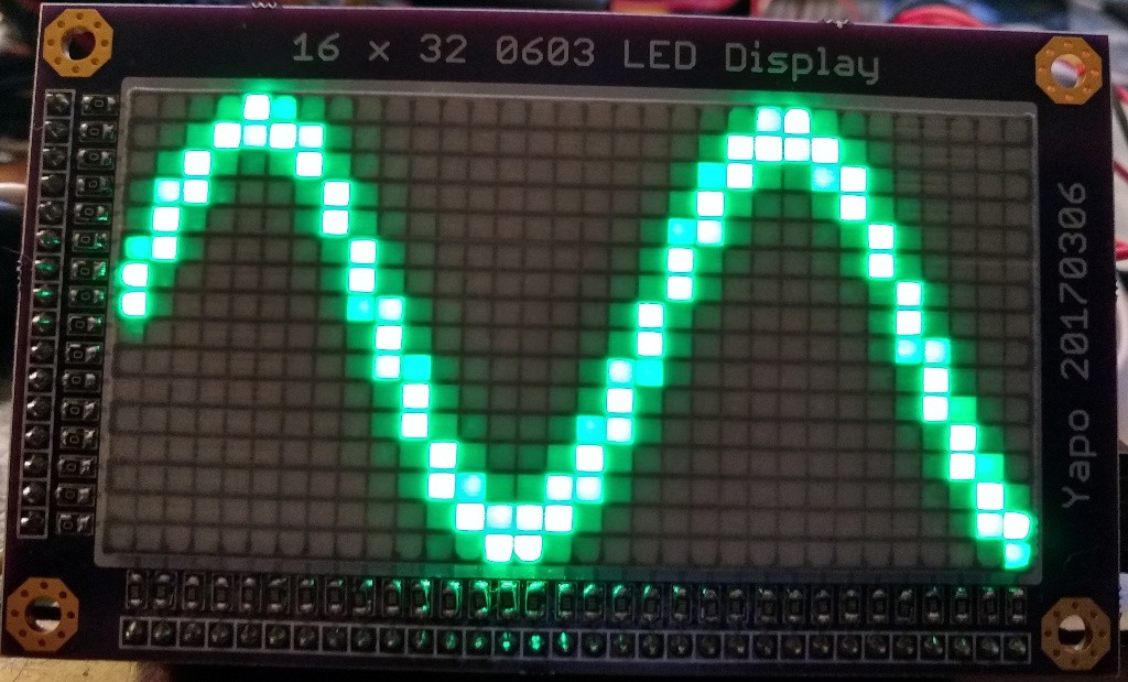
Here's the sine:
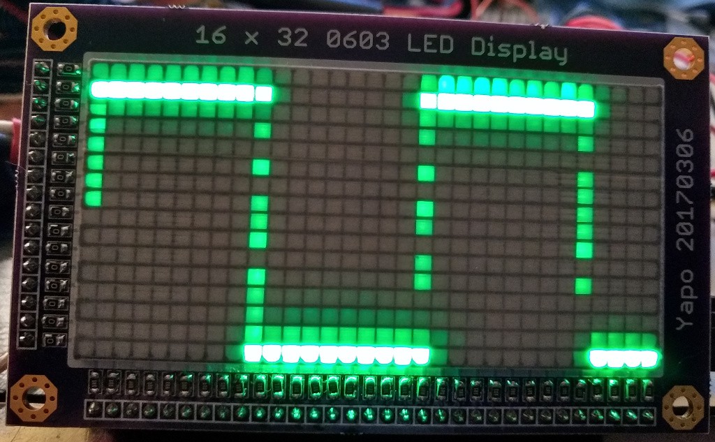
The square wave:
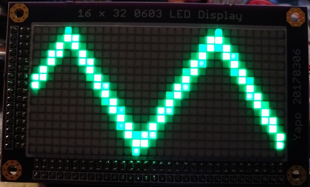
The triangle:
and finally the 20us pulse:
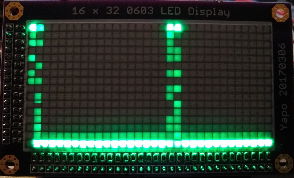
The LEDs turned on in the "vertical lines" are constantly changing, due mostly to trigger jitter. You do get a sense of what's going on while viewing it live, but my camera can't capture a good video of it - sampling issues at work.
The meat of the code is this simple loop:
void scope()
{
  noInterrupts();
  digitalWrite(OEbar, HIGH);
  digitalWrite(PWMbar, LOW);
  while(1){
    uint8_t triggered = 0;
    int val, old_val = analogRead(INPUT_PIN);
    while (!triggered){
      val = analogRead(INPUT_PIN);
      if (val >= 512 && old_val < 512) triggered = 1;
      old_val = val;
    }
    PORTD = PORTD & (0xff - (1<<DAT)); // digitalWrite(DAT, LOW);
    for (uint8_t col=32; col>0; col--){
      PORTB = (PORTB & 0xf0) | (val>>6);
      PORTD |= (1<<CP); //digitalWrite(CP, HIGH);
      PORTD &= (0xff - (1<<OEbar)); //digitalWrite(OEbar, LOW);
      val = analogRead(INPUT_PIN);
      PORTD = (PORTD & (0xff - (1<<CP))) | (1<<OEbar) | (1<<DAT);
    }
  }
}
It samples the ADC in a tight loop, looking for the trigger condition - in this case, when the waveform crosses mid-level. Then, it samples the ADC 32 times, displaying each value as the appropriate LED in that column. There's no way to calibrate the timebase (I guess you could make it go slower if you wanted), and overall the approach is pretty limited.
One thing I learned, though, is that I really don't want to trigger digitally on the output of an ADC - this causes too much jitter. It might be OK if the ADC is running much faster than the sweep, but I think a better approach is a fast comparator circuit.
Starting the sweep exactly on the comparator output is another problem...
Anyway, I think the display shows promise. Now I just have to get it sampling at 20 MHz or so for a real test.
Discussions
Become a Hackaday.io Member
Create an account to leave a comment. Already have an account? Log In.