 Nicholas
TL;DR
I used geared stepper motors, which provide a lot of torque for their size. Drive the steppers with a properly rated stepper driver. Use a microcontroller like the Teensy which has a fast processor, which lets you run Accelstepper fast enough to get the full speed out of your steppers.
Motion Sequence
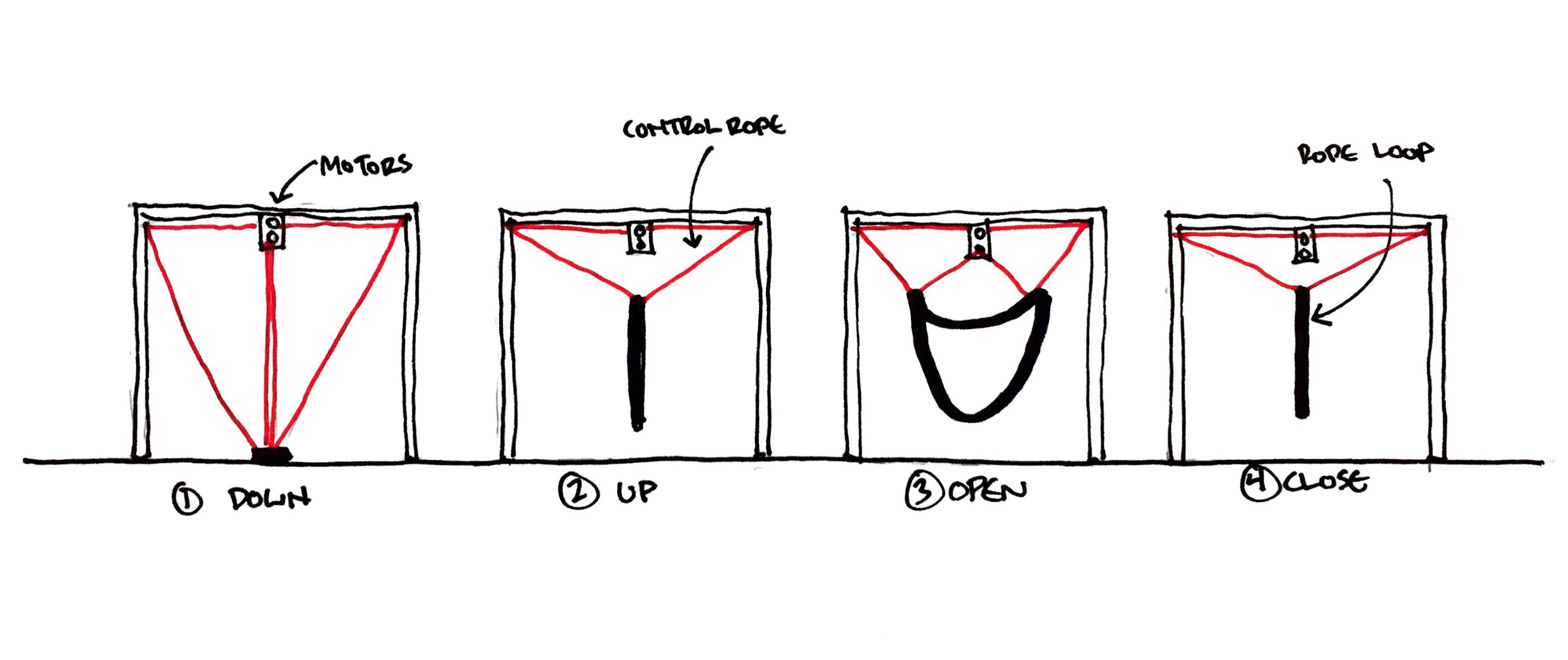
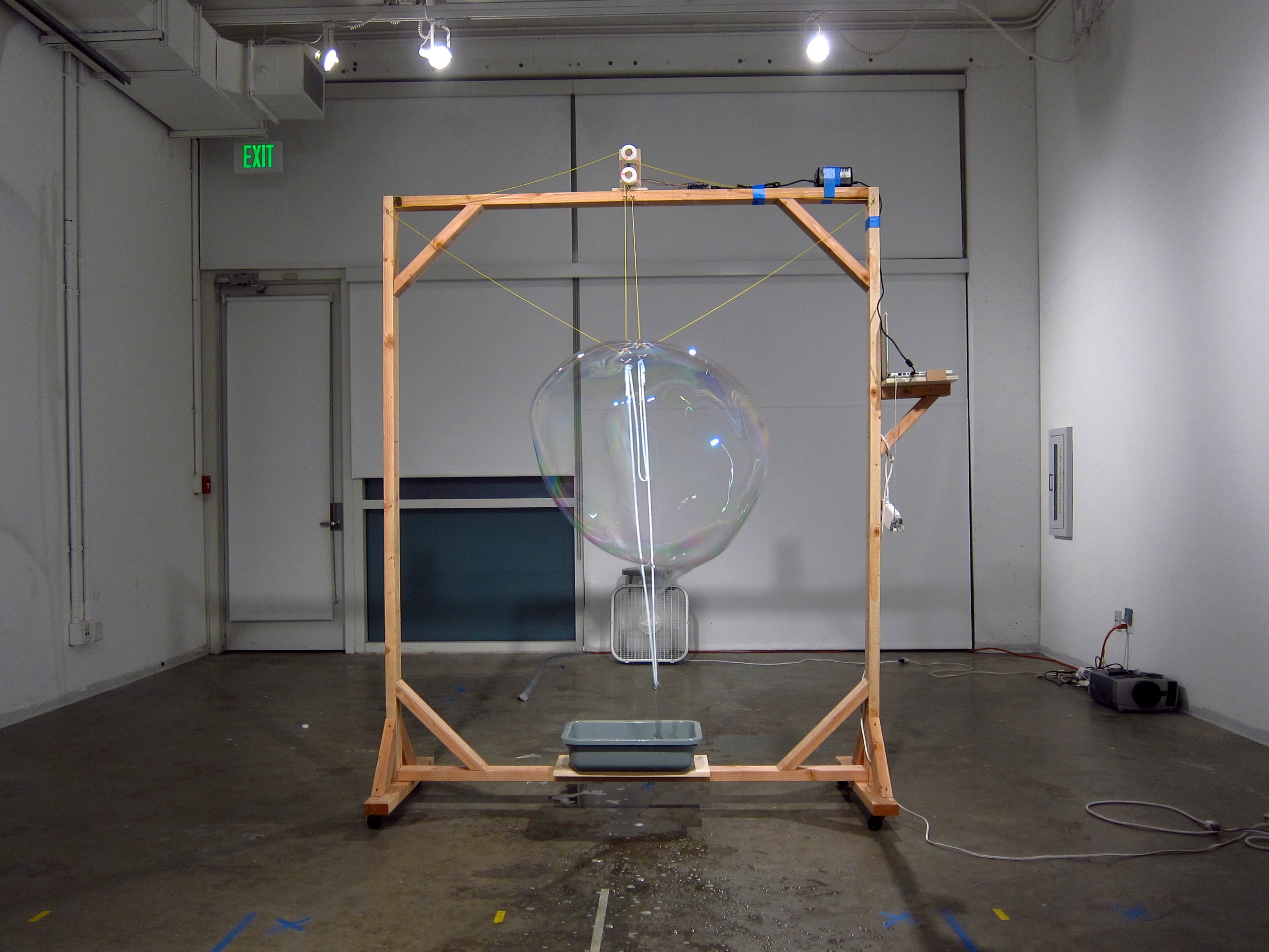
The key to the whole process is moving the rope through a series of positions: (1) dipping into a bucket of soap solution, (2) raising up from the bucket, in a "closed" line configuration, (3) opening into an "open" position (looks like a cartoon smile) to extrude a bubble and then (4) returning to a closed position to cinch the bubble off before returning for another dip in the bucket.
The Pulley System
I figured that I could get the rope to move in the desired manner with 2 attachment points to the rope loop. Each attachment point on the rope loop is a node for 2 control rope lines to attach to it. The control lines pull in different directions, and thereby impart the vertical and horizontal motion needed to manipulate the rope loop as desired.

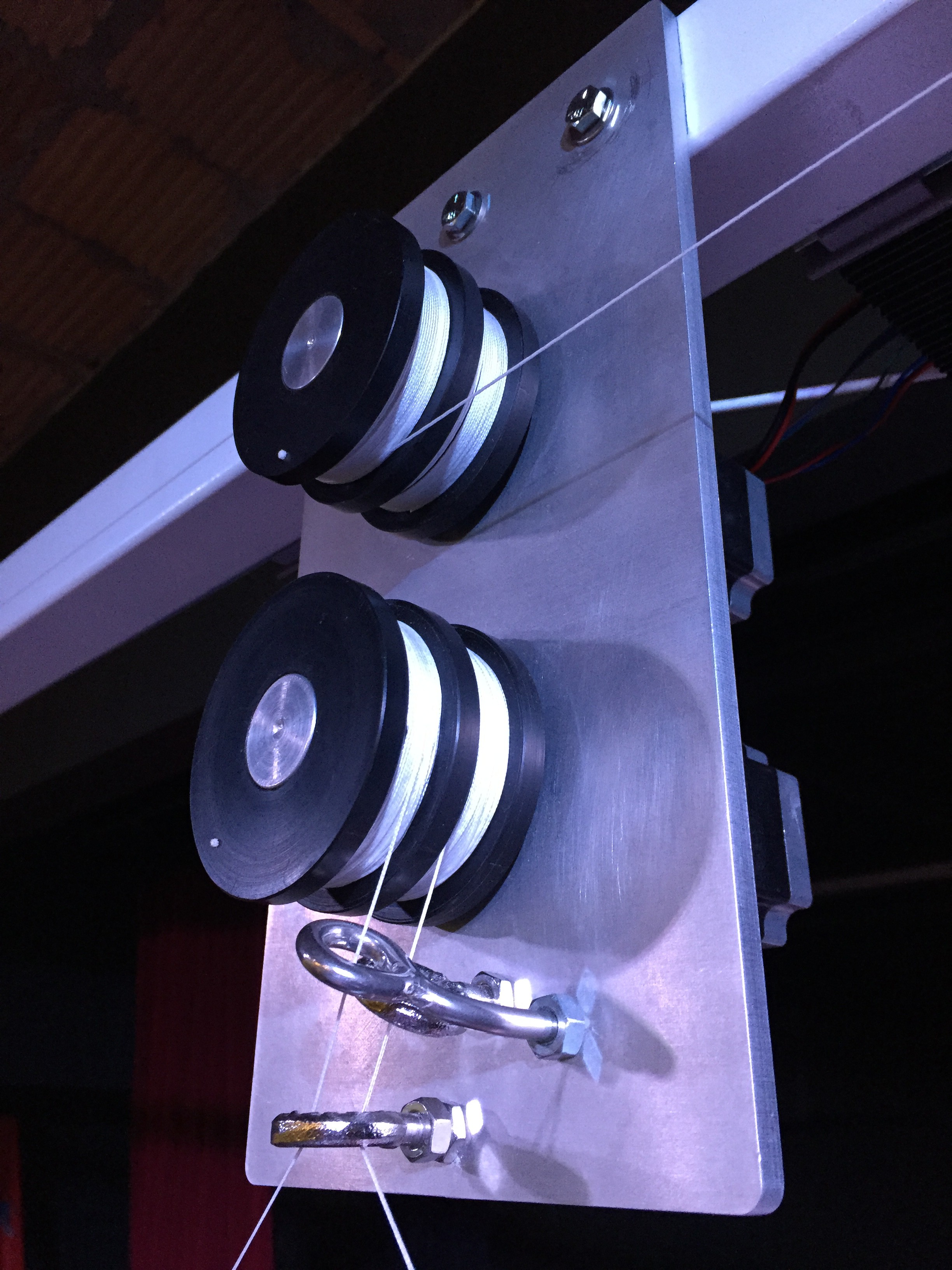
Because the motion of the loop is symmetrical, I can use 2 motors to manipulate 4 control lines. Each motor has a pulley mounted to it with 2 grooves, each groove has a control rope wound in the opposite direction, which route symmetrically to opposite sides of the device.
Motors: the quest for torque
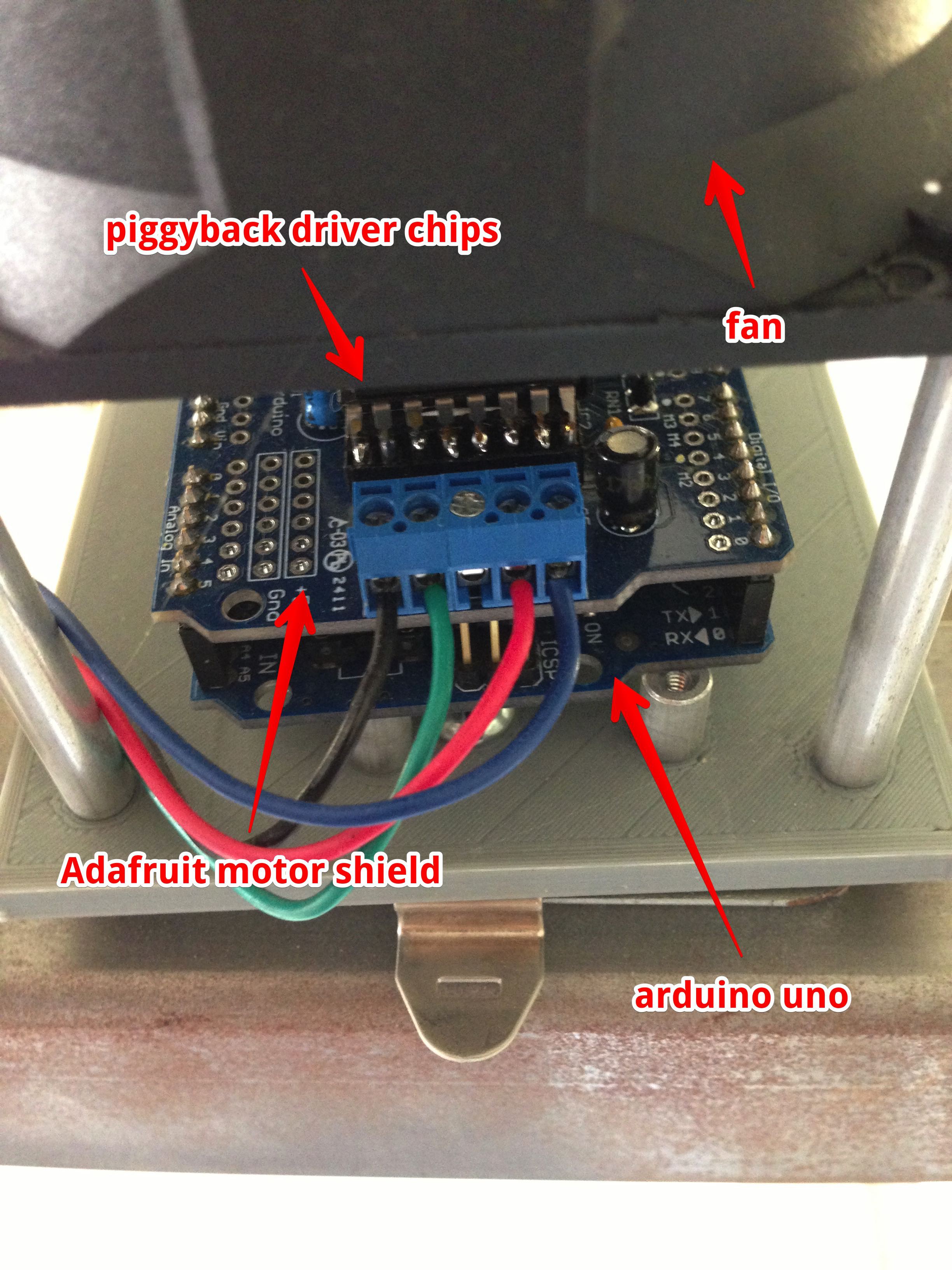
When I built the first prototype of the Bubble Device, I used some NEMA 17 stepper motors I had lying around and hooked them up to an Adafruit motor shield on an Arduino Uno. I sequenced the motion with some spaghetti code. Needless to say, the motors were not adequate to the task. The steppers were rated for 28 oz-in of torque, which was enough to move the rope loop when it was dry, but as soon as you got it wet, the weight was too much, and the motor shafts would slip all over the place.
So, my next move was to get some bigger motors. I jumped up to some NEMA 23 steppers from Sparkfun that had over 4 times the torque (125 oz-in). I wired these up to the Adafruit shield and got some slightly improved results, but not much better than the NEMA 17s. I realized that the NEMA 23 motors were rated for more current than the Adafruit motor shield could provide, so I wasn't getting as much torque out of them as I could. I did some research, and in the depths of an Adafruit comment thread I found a note that you could increase the current sourcing capability of the shield by piggybacking additional motor driver chips (L293D) on top of each other and soldering them all together into a kind of super-bug (or course heat dissipation becomes an issue, so I added a heat sinks and a fan).
With this frankenstein version of the Adafruit motor shield, I was able to get more torque out of the NEMA 23 steppers, and they were adequate to manipulate the rope. Problem solved!
Even more torque
Did I say the problem was solved? Well, it was solved 98% of the time. In some instances, when the control lines were dragging through the pulleys and guides in not-quite-the-right-way, there would be a bit of extra friction, and the motors would slip. It wasn't a show stopper, but over time the rope loop would get out of calibration, opening lower and lower to the floor. Because I was doing short performances of the Bubble Device for only a couple hours at a time, I dealt with the slippage by recalibrating the rope positions every 30 minutes or so.
But in 2016 I was invited to install the Bubble Device at the Taipei Fine Art Museum for a few months! I needed to get my act together and make the positioning more reliable over longer periods of time. I could have done something with closed loop control, but I first tried the more expedient path: throw more torque at it!
This time I specified geared steppers from Phidgets which are NEMA-23 stepper motors with an attached 4.25:1 gearbox yielding 647 oz-in of torque. These motors finally had enough power, and I solved the problem of shaft slippage once and for all.
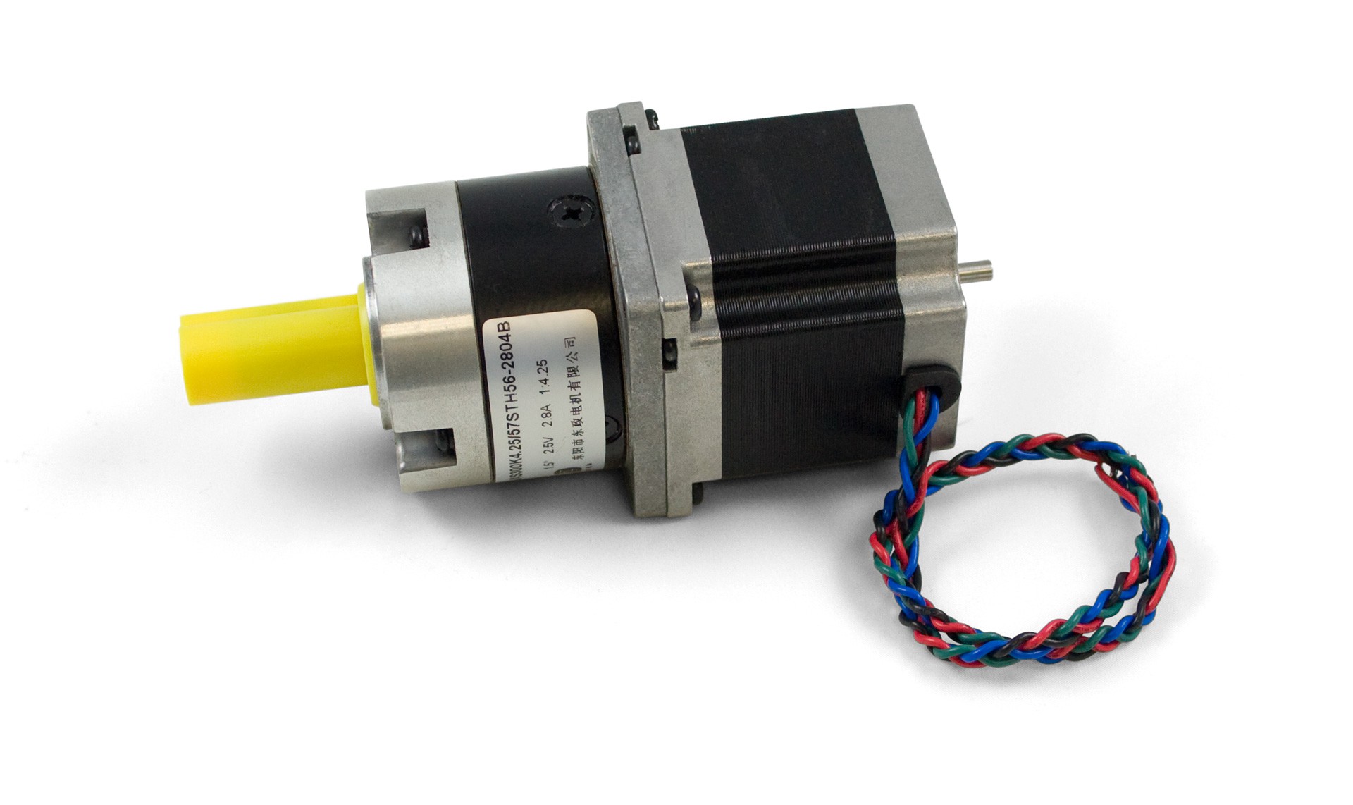
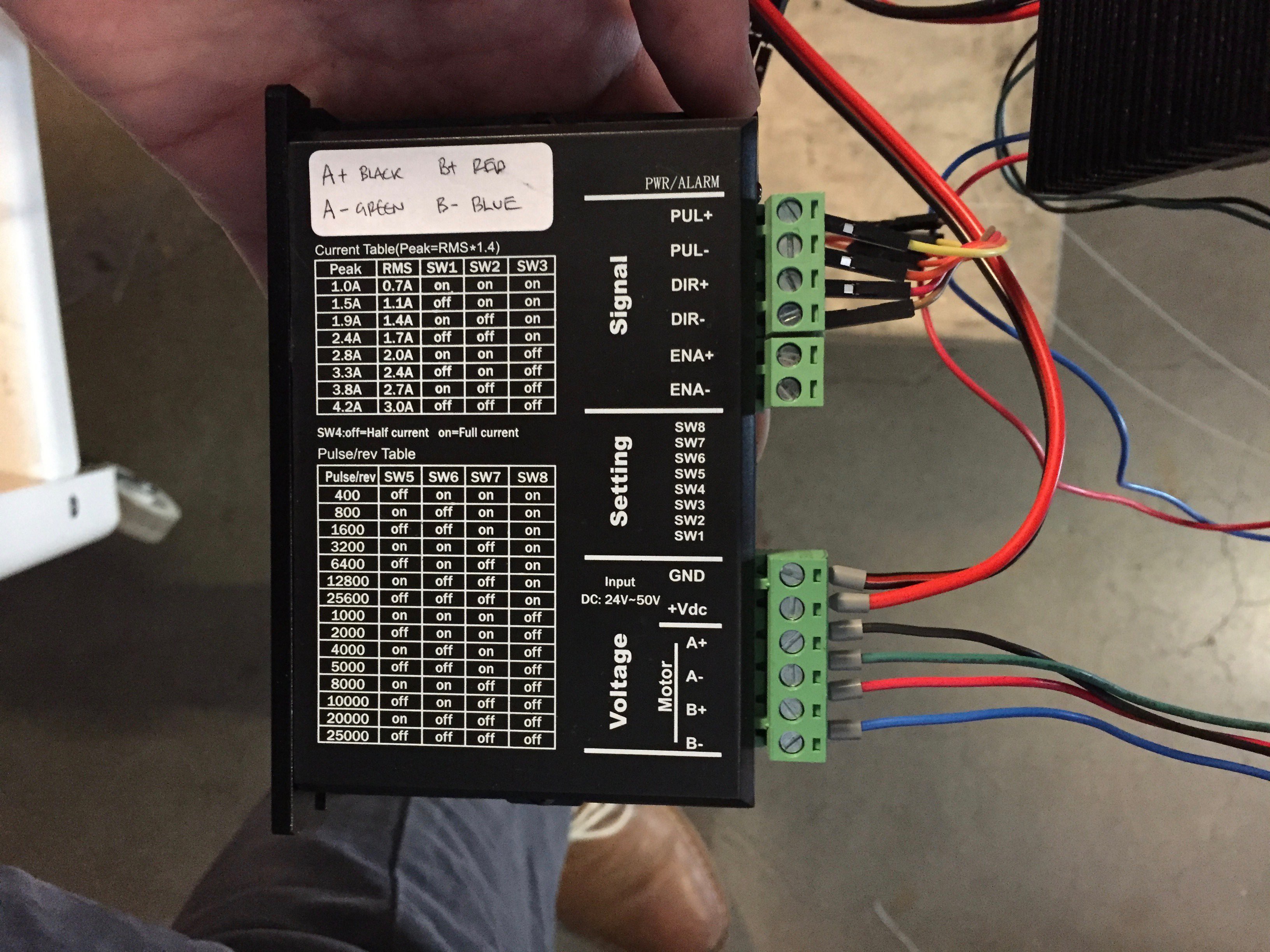
These new geared steppers meant that I also needed to move to a new driver and software solution because they had a higher current requirement than my augmented Adafruit motor shield could deliver. The geared steppers were rated at 12V / 2.8A. I matched them with drivers rated for 4.2A from Lightobject to give plenty of current overhead.
Moving away from the Adafruit motor shield also meant that I had to change my software on the Arduino as well. I had been using the AFMotor library that Adafruit provides for their motor shield. It's stepper functions are basically a wrapper around the well-known Accelstepper library - so I rewrote my code to work directly with Accelstepper instead of relying on the Adafruit wrapper.
On the previous non-geared steppers, I had been limiting the top speed to avoid slippage (as torque declines with speed). With the geared steppers, I had enough torque to move at higher speeds. This is desirable, because once you've dipped the rope loop in solution, you don't want to dawdle. You just lose bubble solution to dripping and evaporation if you take too long to open the loop in front of the air current.
More MHz!
This is where I hit a new limitation of my setup: the processor speed of the Arduino Uno! Stepper motors need to be constantly fed with pulses to tell them to move. The Accelstepper library performs repeated calculations to feed these pulses out with the correct timing to give a smoothly accelerated motion curve. If you command the motors to move at too high a speed, the rate at which pulses need to be sent out to the motors exceeds the refresh rate of the Accelstepper code running on the Arduino. You notice this when your motors hit a sudden speed limit before the acceleration curve has tapered off at its maximum speed.
This problem is more acute when using geared steppers. The gear box reduces the rotation of the input motor. The 4.25 ratio of the gearbox I used means that I need to pulse the motor 4.25 times to get the same rotation output as a single pulse to an un-geared stepper.
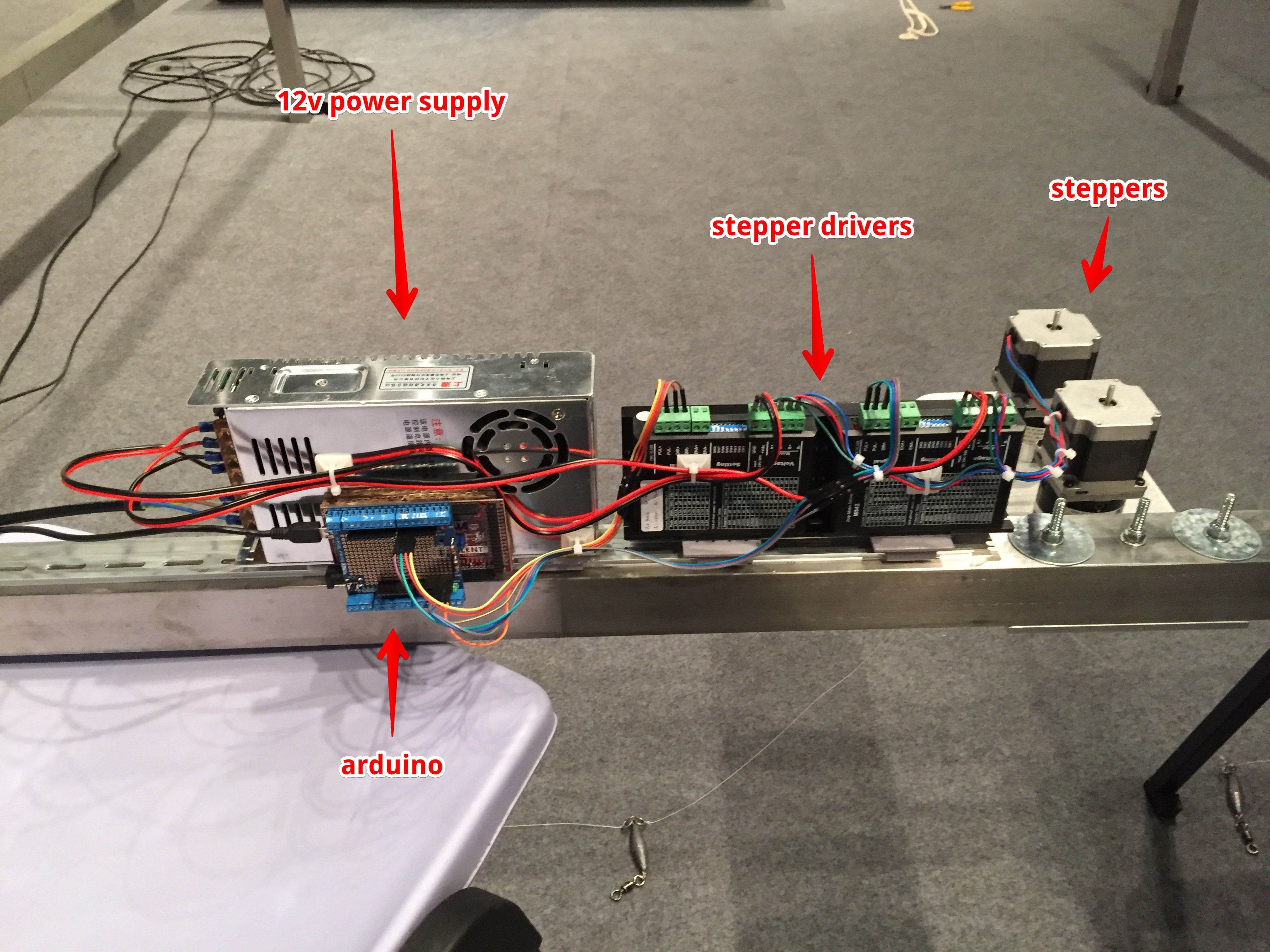
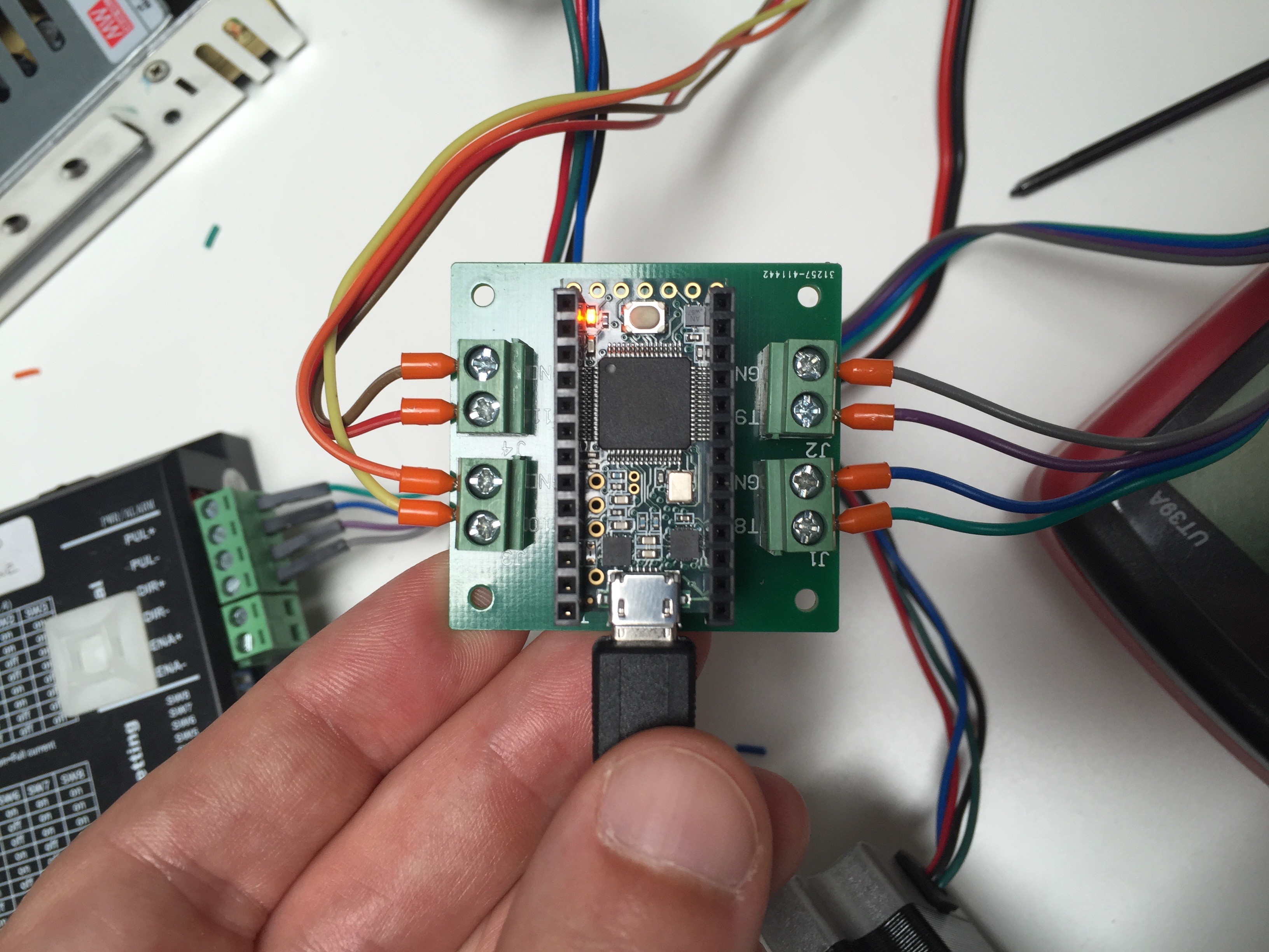
The Arduino Uno runs an ATmega328 at 16Mhz. I borrowed a friend's ChipKIT Max32, an arduino-compatible board which runs a PIC32 at 80 MHz. Sure enough, that allowed me to hit higher max speeds on the motors because of the higher MHz and therefore higher Accelstepper refresh rate. I eventually settled on a Teensy 3.1 which runs a Cortex-M4 at 72 MHz. It was cheaper and smaller. I also designed my first PCB: a simple little carrier board that the Teensy plugs into which breaks out some pins to screw terminals.
So, that's the setup as of today (January 2017). This is a learning process that's taken me a few years, as opportunities have appeared to show the Bubble Device. Each time I have a chance to show it, I try to focus on improving one small part of it.
Code
I included my code if anyone is curious to see how I worked with Accelstepper. The timing for the motion control and set point calibration is done on a laptop which sends serial commands to the Teensy. So the code on the Teensy side is a pretty straightforward set of motion control commands in response to external triggers (I used the CmdMessenger library for this).