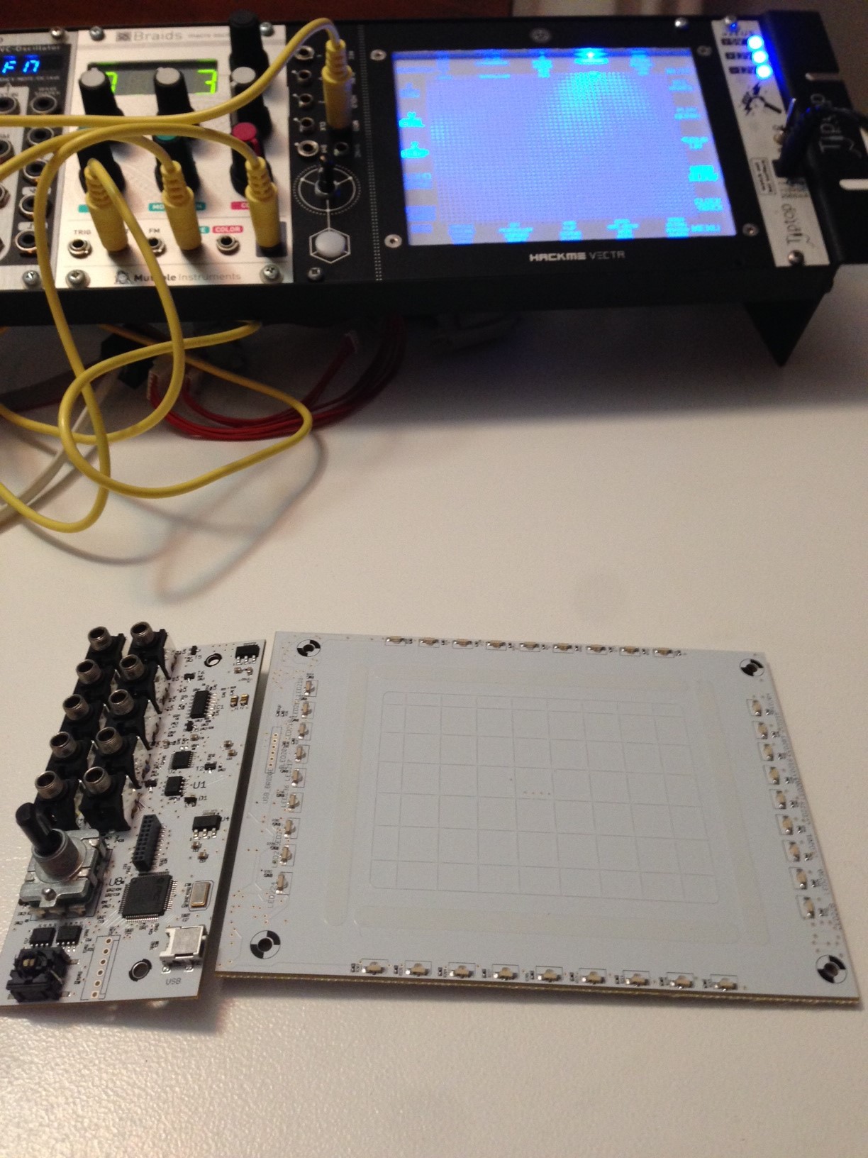
As soon as a I saw Microchip's new 3D sensing technology, I knew immediately what I wanted to build. I imagined controlling audio with a whole new level of precision with huge dynamic possibilities. I've spent the last year developing it, coming up with ways to expand the musical possibilities and the usefulness of Vectr as an instrument. But, Vectr is also open source hardware and software, so you can use any of its functionality to suit your own purposes. I have imagined all sorts of applications for this technology, and time willing, one day I'll make them. It's very intuitive to play with. The results of your actions are immediately apparent. It's amazing how quickly this new interface technology becomes natural.

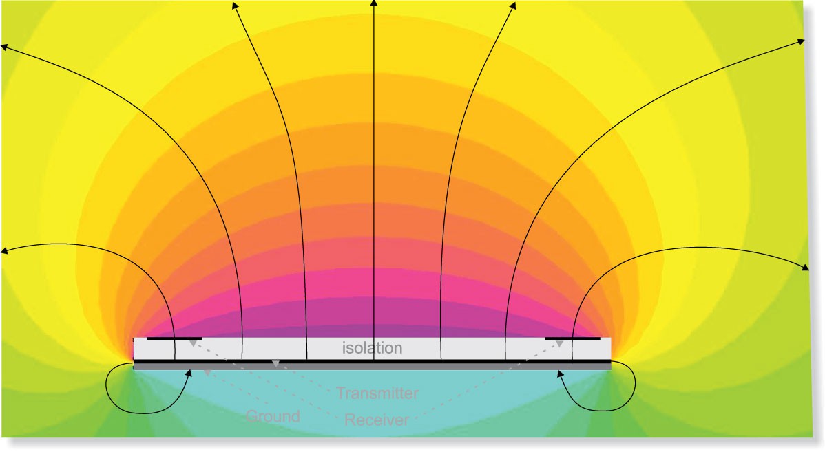
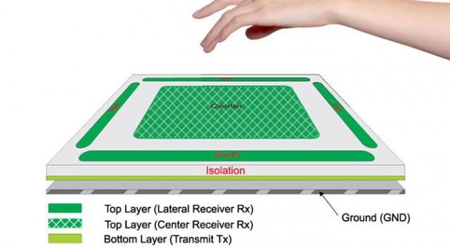
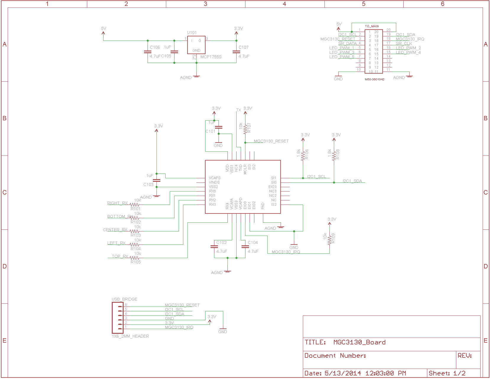
Vectr uses Microchip's MGC3130 3D sensing technology with a custom developed sensor circuit board. It's able to resolve the position of an object over the sensor in a volume which is about 3.5inx3.5inx6in with 16 bit precision. I read this data using a PIC32 microcontroller, which is running FreeRTOS. The microcontroller manages all the system tasks, interacting with all the peripheral integrated circuits and controlling all the different operational modes. The 3D sensing is performed using capacitive sensing several orders of magnitude more sensitive than a capacitive touch screen. Using multiple electrodes all being affected by the same transmission, the sensor is able to detect the location of disturbances in a static electric field.
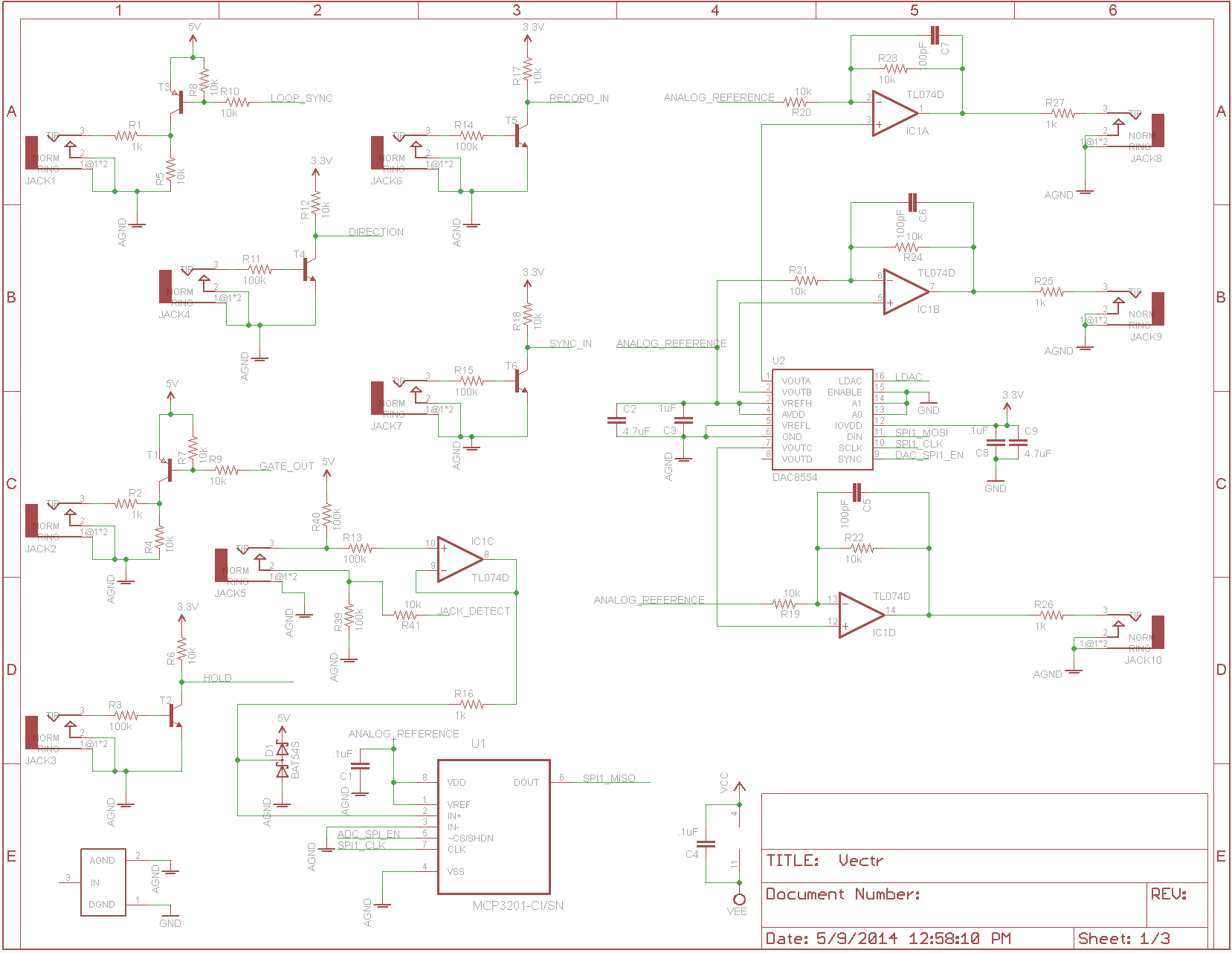
Vectr uses a quad 16 bit DAC to generate analog control voltages in the range of -5V to +5V. There is one analog output for each of the cardinal directions of the 3D sensing.
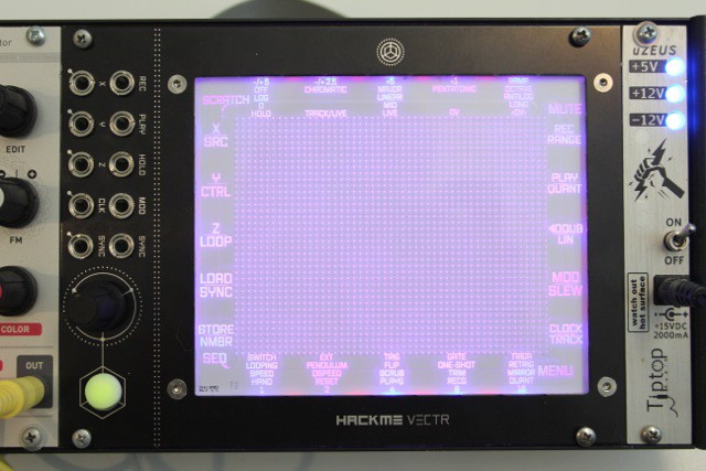
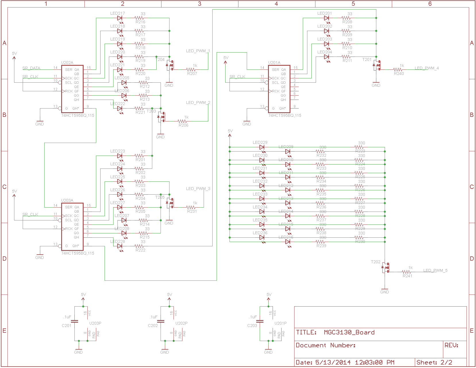
Vectr uses 36 LEDs for visual feedback. They change in brightness relative to the position of the object in front of the sensor. They are right angle LEDs mounted around the perimeter of a piece of laser cut acrylic, in which dots have been laser engraved in the front to create a 3D floating effect. The LEDs are multiplexed using shift registers and MOSFETs driven with PWM signals from the microcontroller. The brightness algorithm and LED driving is actually a fairly intensive process, but the result is quite mesmerizing.
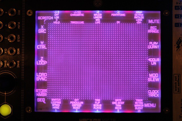
The LEDs are also used to indicate progression through the menu system which allows the user to change all sorts of parameters and behaviors. Each of the analog outputs is independently configurable. The analog output ranges can be scaled and limited to ranges like 0 to +5V or -2.5V to +2.5V, etc. The analog outputs can be quantized so that the voltage fall on note values in a 1 Volt per Octave scheme. The notes can be on different scales like Chromatic, Major, or Pentatonic. Combining the range settings with quantization you can play scales of different octave lengths. Setting all three outputs to quantization and playing multiple oscillators can have quite astounding results.
Vectr can also record sequences of hand movements. It contains serial SRAM to record for up to 50 seconds. It stores the raw data from the 3D sensor so any parameter available in the menu system can be adjusted after the sequence has been recorded. This provides for massive facility to record and then manipulate the sequence live. The user can speed up and slow down the sequence by making circular gestures, clockwise for faster and counter-clockwise for slower.
Vectr has an overdub capability where you can re-record each of the outputs individually without affecting the others while they are playing back. This way you can create dynamic sequences with continuity. Then, Vectr also has flash memory for storing the sequence to bring it back later after power down. Vectr can hold up to 5 recorded sequences, which can easily be recalled at any time. Each of the recorded sequences stores all the menu settings with it.
Then, there are performance modes. There is sequencer mode, where you can access up to four recorded sequences quickly and switch between them seamlessly. There is quick mute mode where you can turn on and off individual outputs. There is the previously mentioned overdub mode. And finally, there is "scratch" mode where you can play a sequence forwards and backwards and at different speeds with hand movements.
Vectr also can read one analog voltage from 0 to +5V. This voltage input can be used to manipulate the analog outputs and vary playback parameters, like the speed of playback, the end of the loop, or the present position in the loop. Sending an oscillating voltage into this input can have some stunning sonic implications.
All of the previously mentioned behaviors can also be synchronized with external signals. Using rising edge triggers, things like the start and end of recording, or the start and end of playback or overdubbing can be precisely controlled externally to make perfectly synchronized loops. Vectr has a similar ouput capacity to send timing information to other modules, so Vectr can be used as a centerpiece in a modular synthesizer arrangement. It can synchronize the rest of the system to its playback.
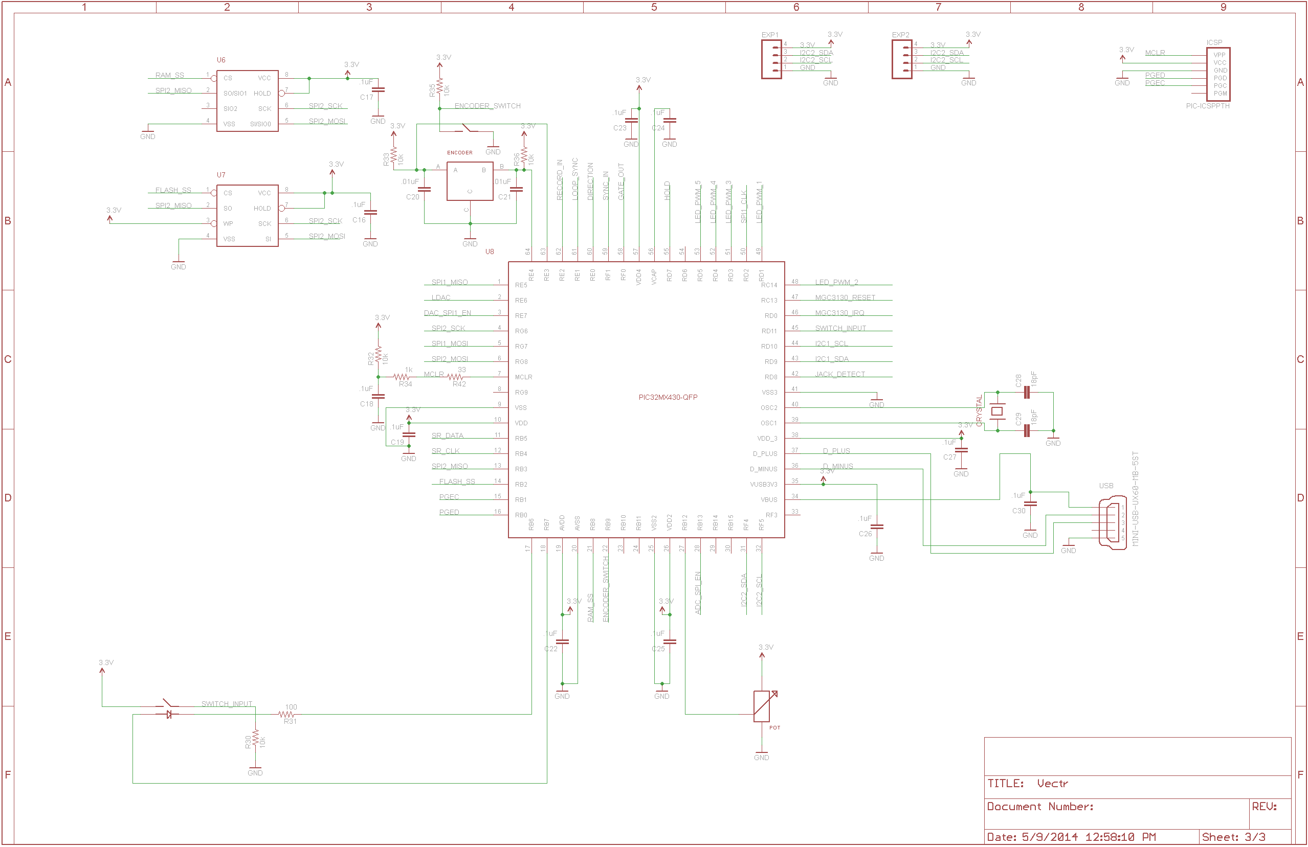
Here's some more information about Vectr's hardware design. Vectr contains two circuit boards. One for the sensor and LEDs and one with basically everything else: microcontroller, memory, DAC, ADC, jacks, analog circuitry, power circuits.
This schematic shows the MGC3130 sensing circuit. It also has the low-PSRR regulator for a nice quiet power supply and a connector which passes the signals between the circuit boards.
This schematic shows the LED multiplexing scheme. There are 36 LEDs grouped on three shift registers. The LEDs are then grouped into groups of five for a MOSFET. Each LED is on only 1/5 of the time and FET duty cycles are driven by PWM from the microcontroller.
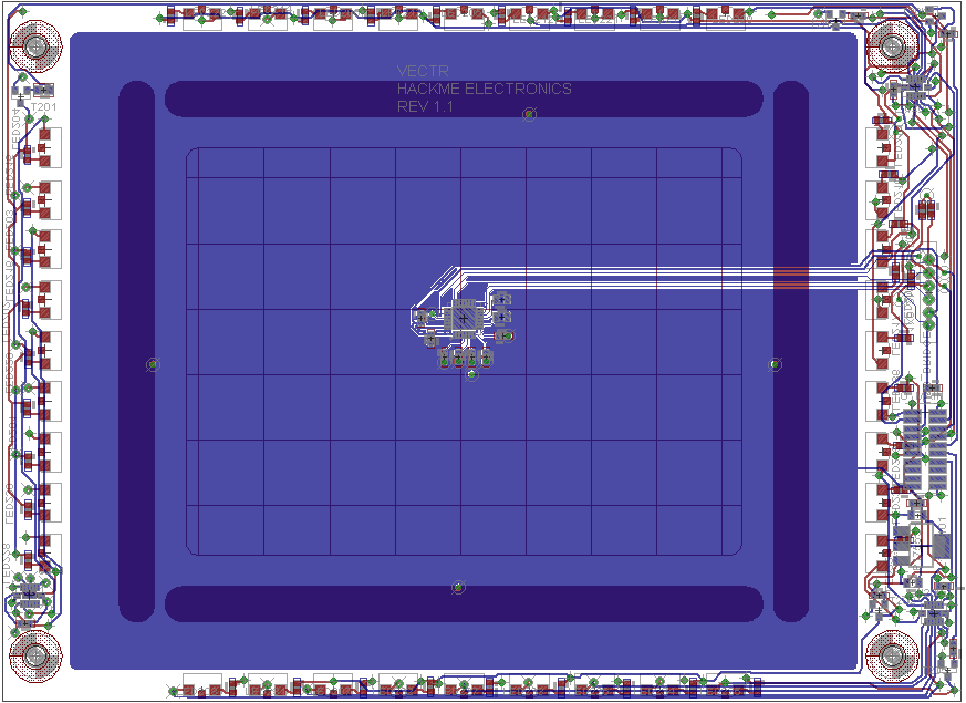
Here's what the board looks like that contains the above two circuits. The sensor is formed by the electrodes which form a square around the center. The sensor IC is mounted on the back in the middle of the sensor. Around the outside are all the LEDs and all the multiplexing circuits.
This schematic shows Vectr's analog circuitry with the quad 16-bit DAC, the ADC and the signal conditioning circuitry for getting the analog signals in and out. The analog outputs can range from -5V to +5V and the other inputs are level shifted to protect the microcontroller from being overvoltaged.
This schematic shows Vectr's microcontroller, a PIC32 micro. It also shows the RAM and Flash memory, as well as the illuminated switch and rotary encoder.
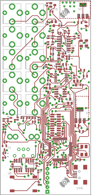
Here's what the main board looks like. The microcontroller is near the bottom. The jacks are all arranged on the left in two columns. To the right of them is all the analog circuitry.
Vectr's firmware is written in C and uses FreeRTOS. I enjoy using an RTOS as a fundamental programming structure. Not all programs call for one, but Vectr has a lot of multitasking to do with the interface, memory, data conversion, and processing to do. I wrote a blog post a while back describing the fundamentals of working with an RTOS in an embedded system. Check it out over here: http://hackmeopen.com/2013/02/freertos-getting-to-know-you/
I've structured Vectr's software to contain a task for each major function and to make fairly heavy use of interrupts for letting the system know when a hardware task has been completed or some hardware parameter has changed. For instance, the MGC3130 needs to be read. It signals the microcontroller when data is available. This signal is fed to an external interrupt on the microcontroller, which then sends a semaphore to the MGC3130 task to read the data over the I2C bus. There are a number of stages in the I2C process. Rather than stalling the microcontroller to wait for each stage to complete, Vectr uses the RTOS functionality of semaphores to cause the task to wait, ceding processor control to other tasks. This design methodology runs throughout Vectr's firmware for tasks which handle, the DAC and ADC, the memory communication, the menu system, the switches, and the control inputs.
I've tried to write it in a legible way, breaking functions into pieces when necessary, but there's quite a bit of necessary entanglement between functions as some dependency is required. Nevertheless, the MGC3130 driver is totally encapsulated and free to use.
License
Vectr's software is released under the Modified BSD License. I negotiated this arrangement with Microchip after discussions with their legal department. This license allows Microchip's copyrights to be protected. They are willing to share their code but they don't want it used on competitor's microcontrollers. My portion of the code is free to use as is the hardware.