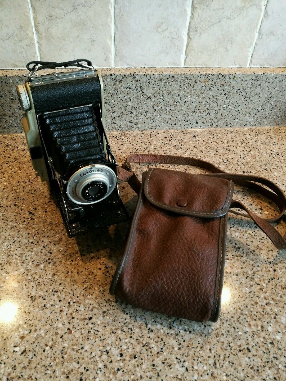
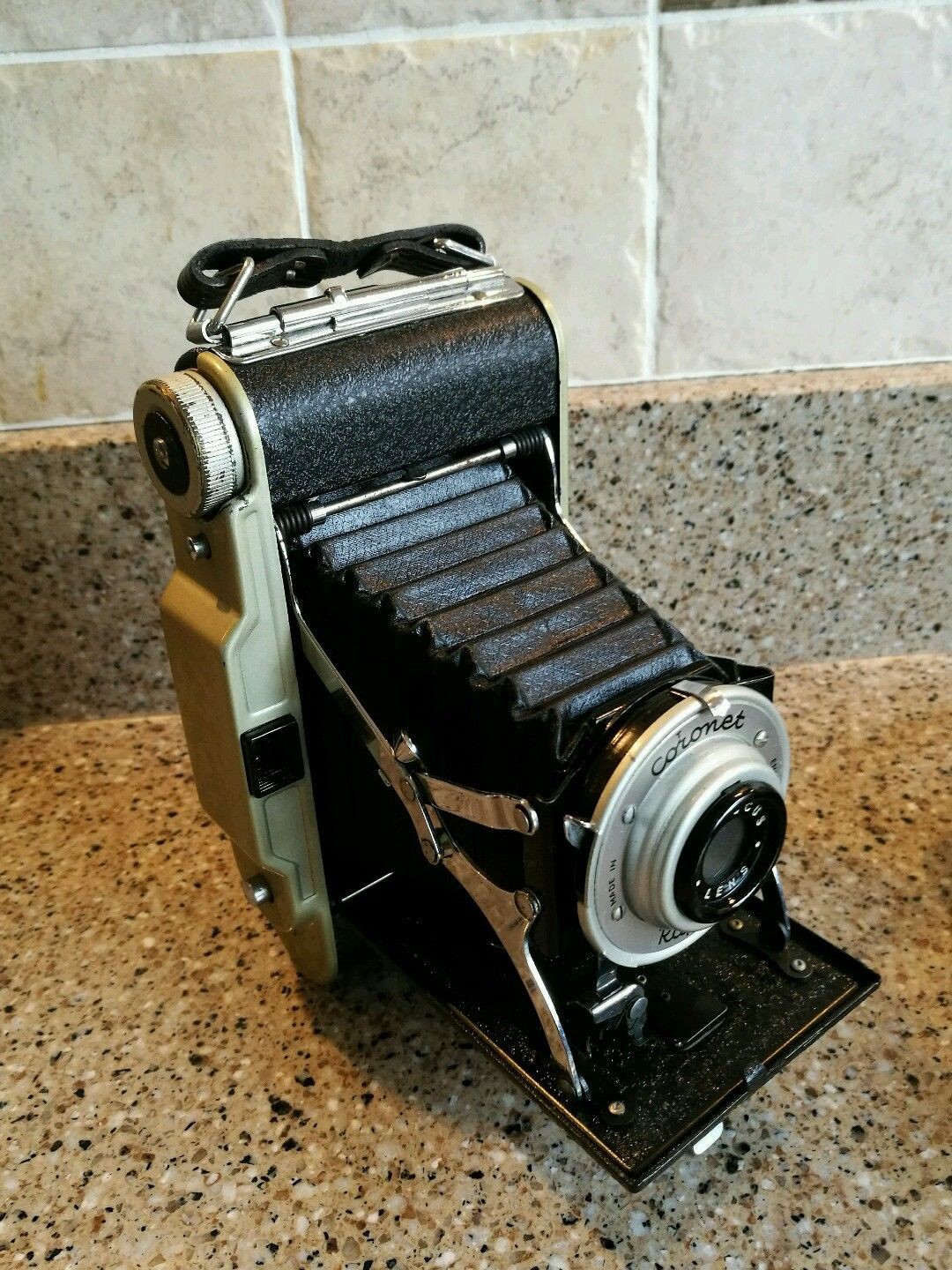
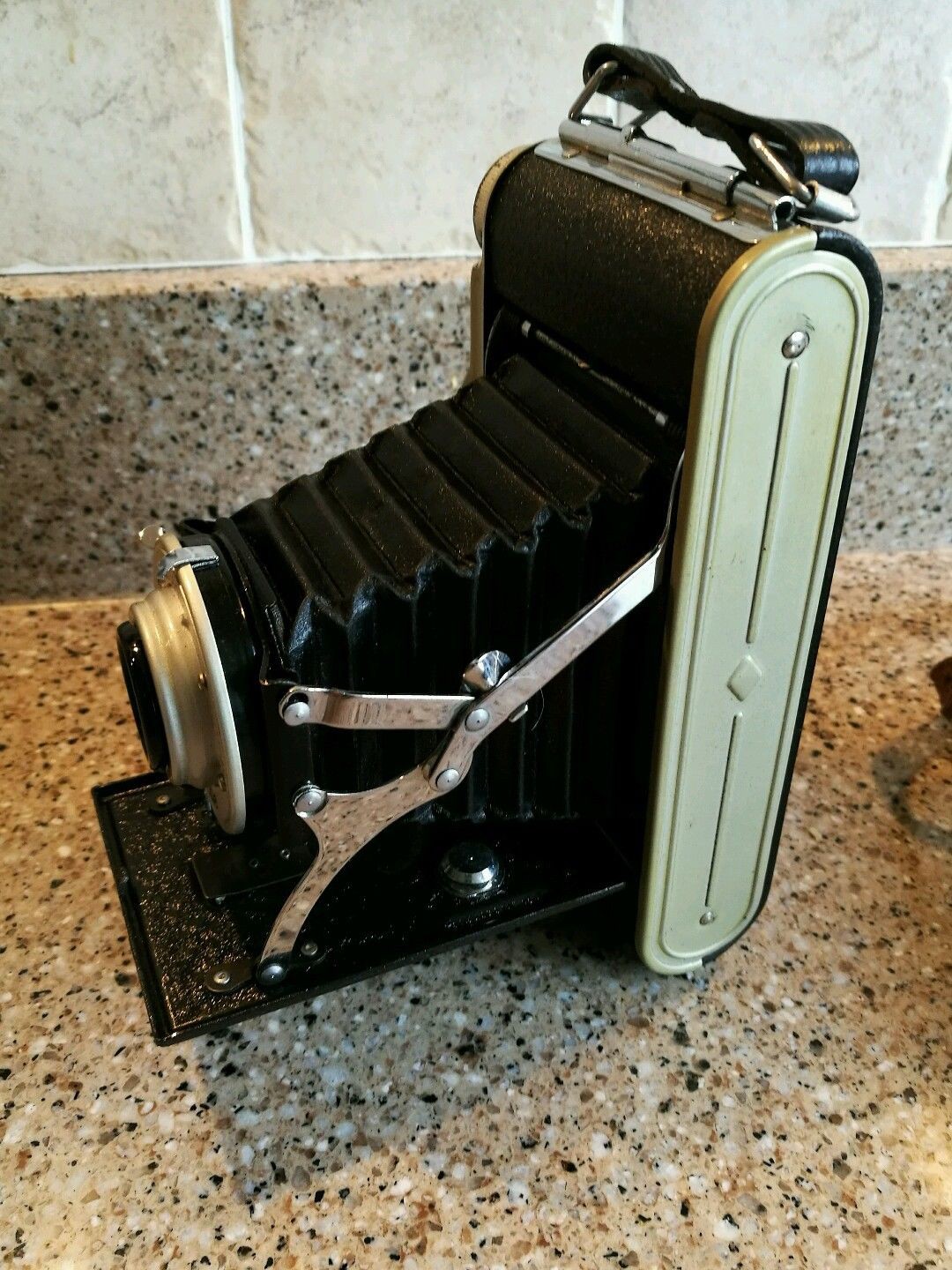
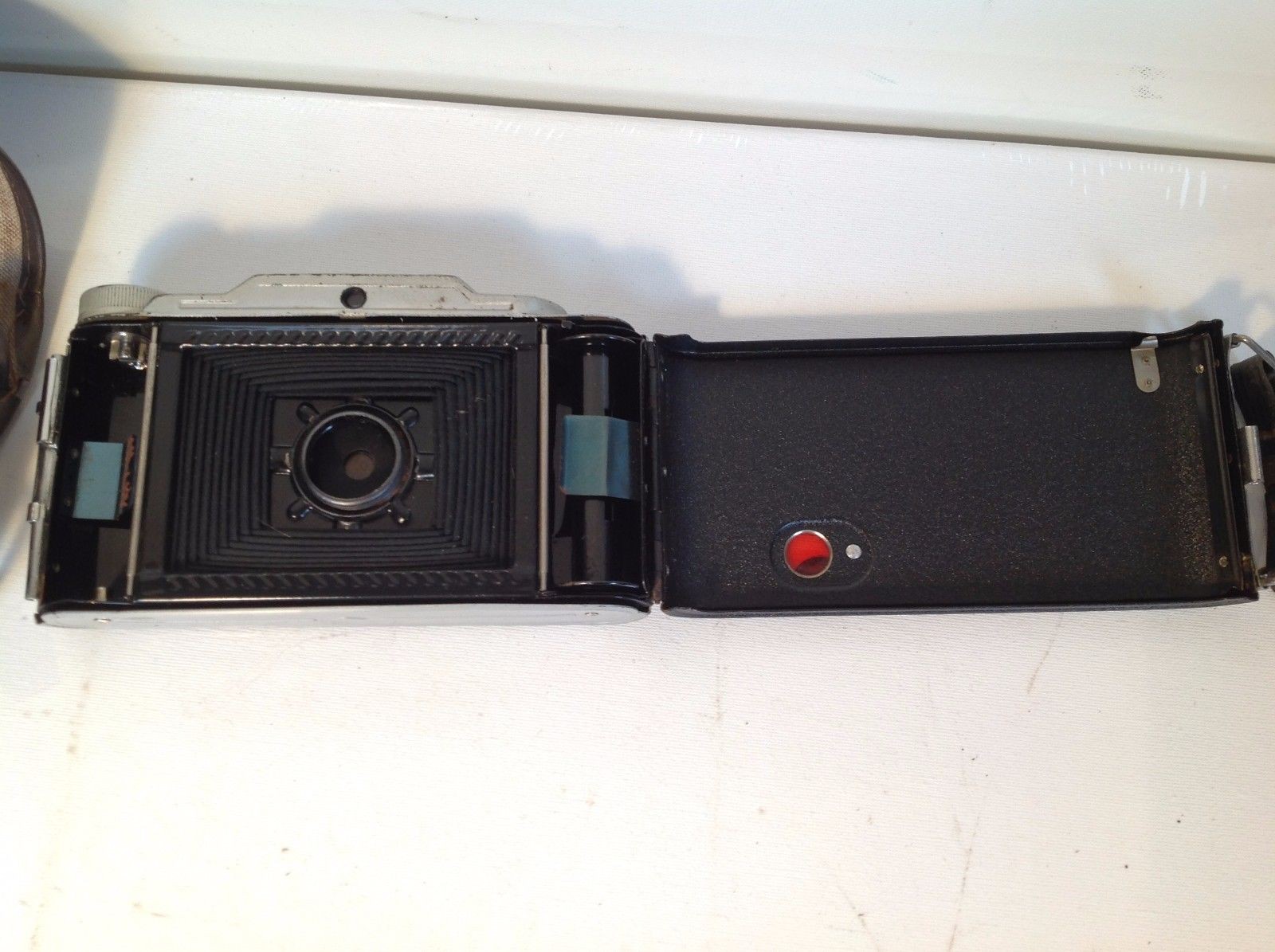
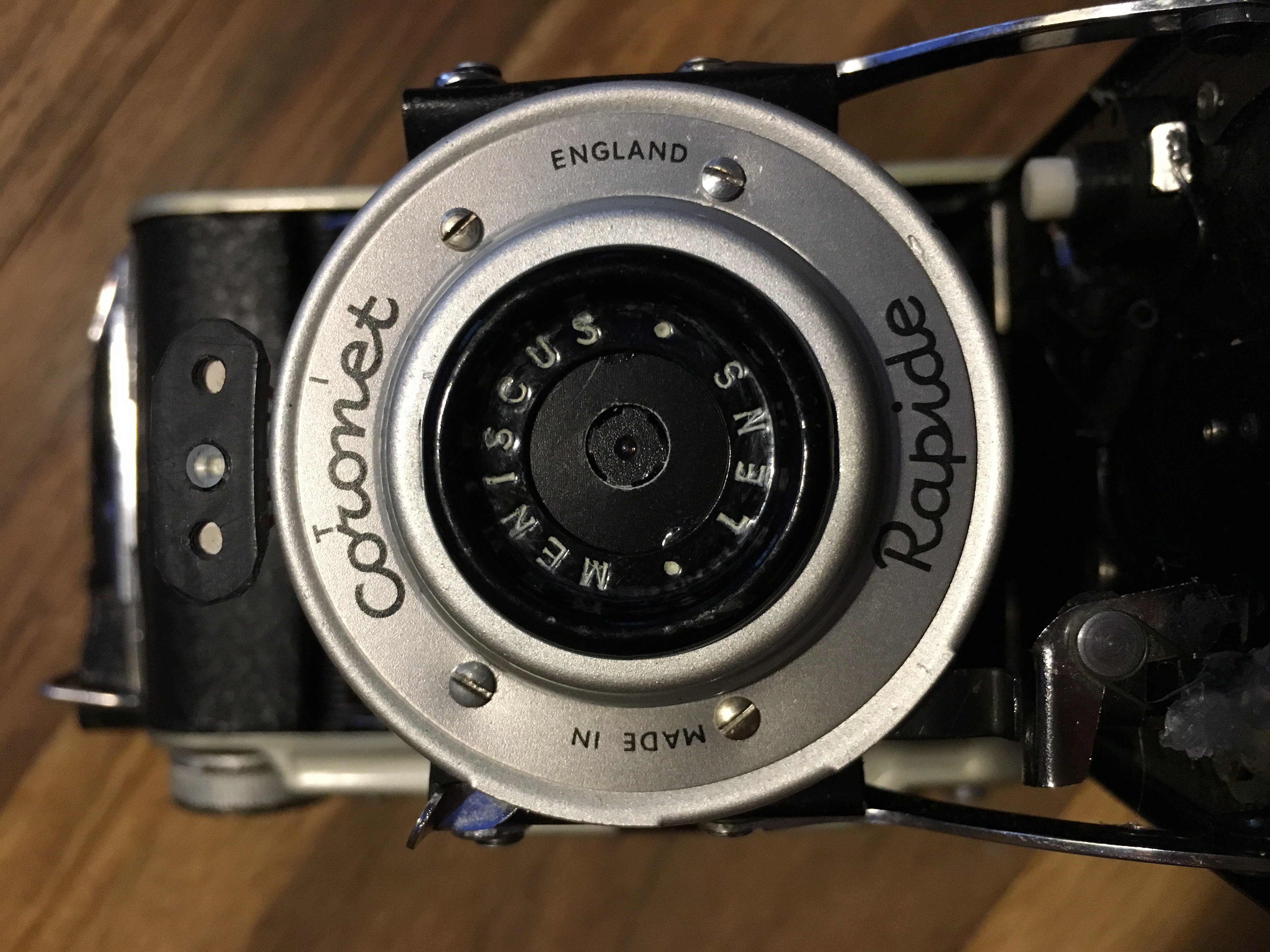
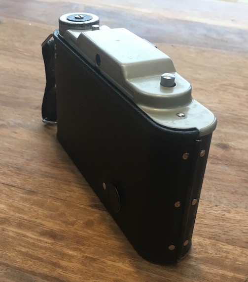
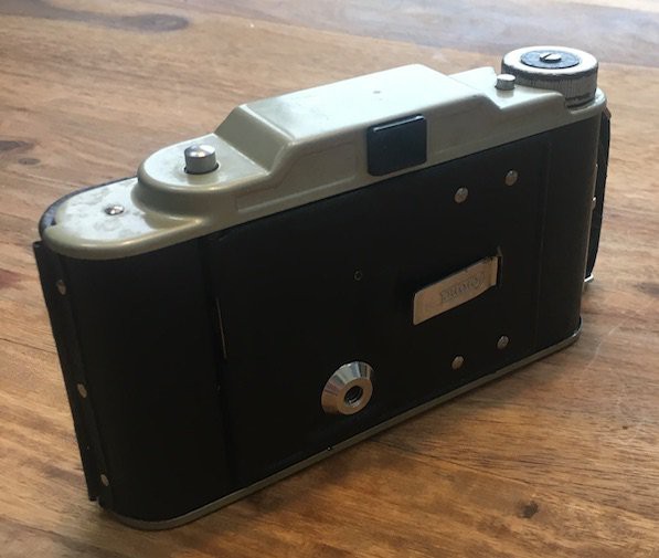
For the next instalment, I wanted a more interesting original camera/enclosure. Thanks to good old eBay I found a folding camera called the Coronet Rapide from the late 40s/early 50s that looked cool and was in my price range - It cost me the princely sum of £9.99 (plus postage).
|
|
|
|
|
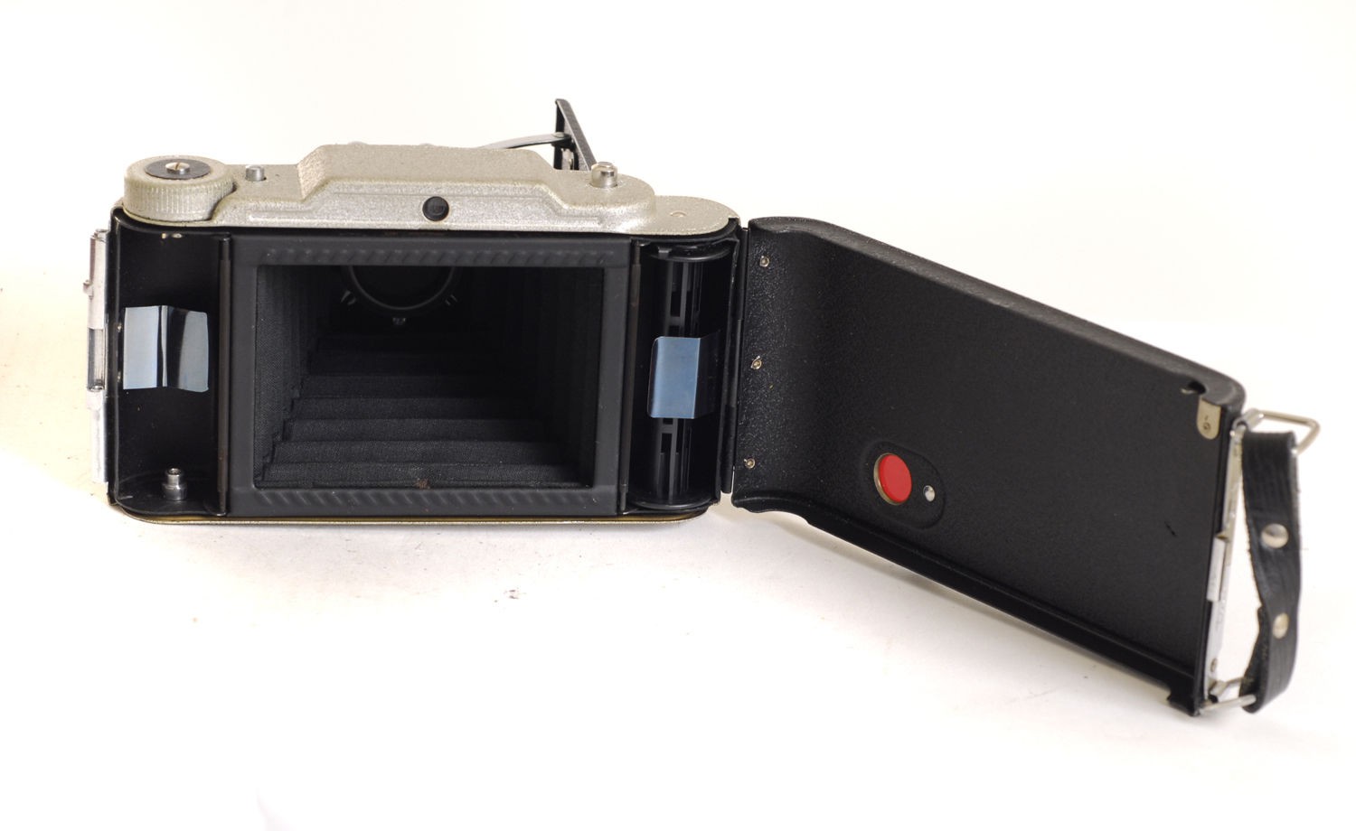
I wasn't sure of the dimensions of the camera but I was hoping that I could fit cylindrical power cells of some type into the two sides where the film used to fit and have room for a Pi Zero to lie flat between the collapsed bellows and the rear case. I also hoped that the lens/shutter assembly would have enough room to house the camera module. Some of these things happened others didn't quite work out that way, read on for more info on that.
Power
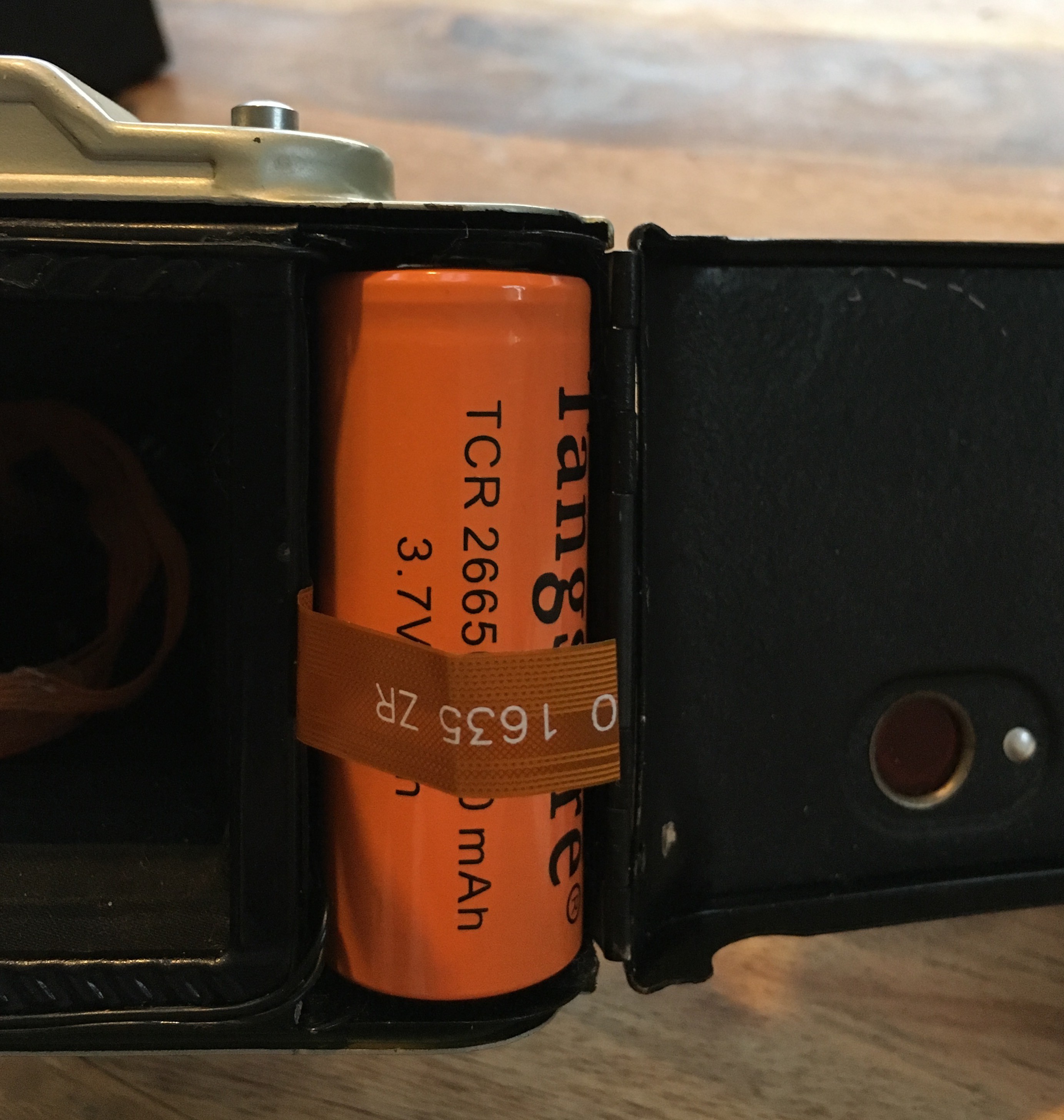
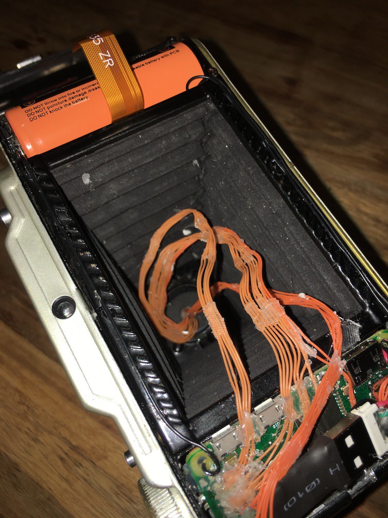
Luckily, as I'd hoped, the recesses that were originally designed to hold the 120 film were a perfect fit for a 26650 Lithium Ion cell. The ones I used have an integrated protection circuit to protect them from short circuit, overcharge and over discharge. I fashioned some contacts out of some of the springy metal found in a used film pack from the Polaroid camera and fixed them in position with a little hot glue (LOTS more of that coming up). I also used a piece of ribbon cable to make a battery release tab which I attached to a conveniently located hinge that used to support the film spool. As there is no integrated charging functionality and I wanted to make the batteries replaceable, this makes it really easy to swap them out.
|
|
The battery is wired via a mechanical switch to a 5v boost module, this one to be exact. I chose it mainly because of its high power output (it was going to be supplying a Pi, WiFi + Bluetooth Dongles plus a Flash of some sort so 3A should cover it).
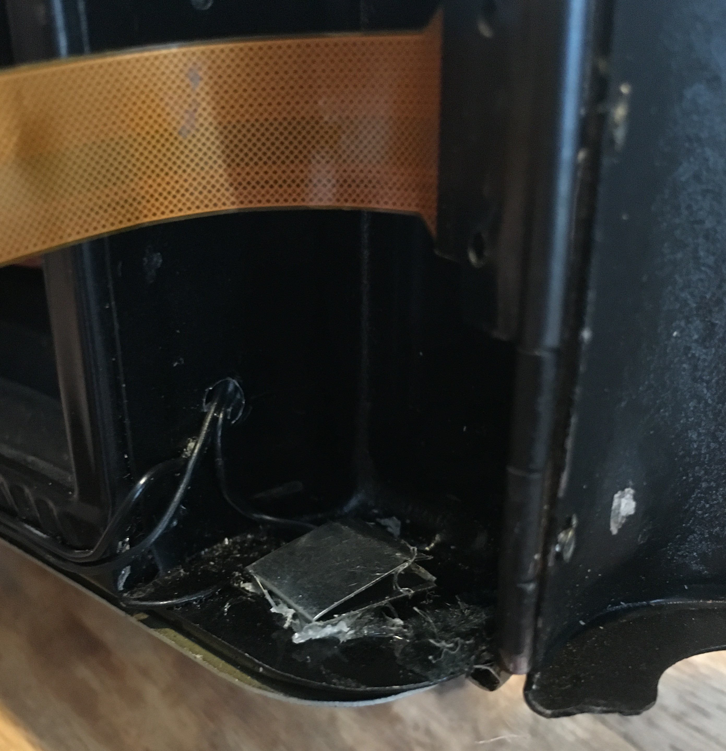
This switch was 'borrowed' from a magnetic LED work light. I used other microswitch types but they weren't sturdy enough. This one will stand up to a good amount of use. It is mounted (via hot glue!) in such a position that it doesn't get in the way of any of the mechanics of the bellows system and nestles in a void when the camera is closed. Due to some design changes during the project,, the switch cuts the ground line rather than the conventional live but electrically it makes no difference.
The Camera Module
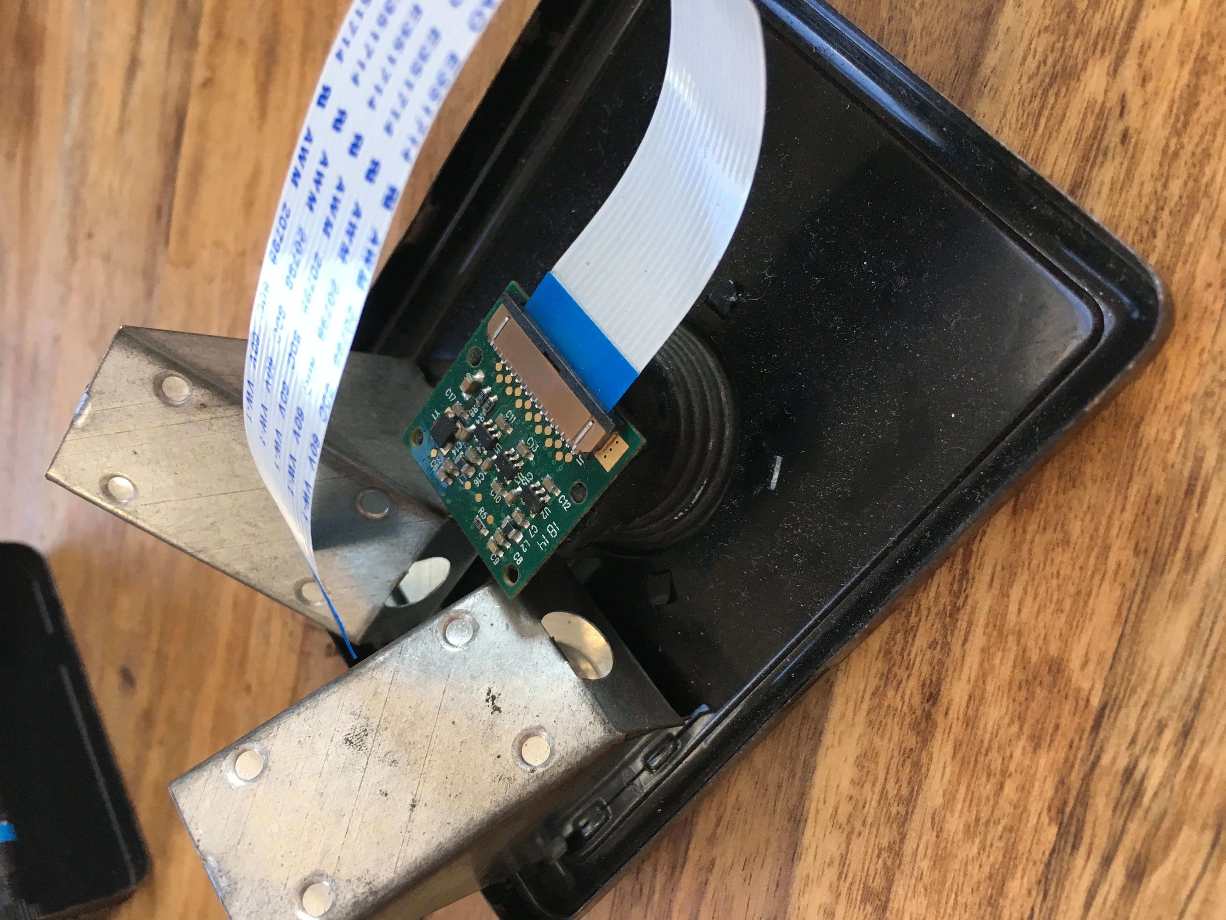
My luck was in again as the camera module was an almost perfect fit for the lens assembly and I could leave most of the original shutter mechanics in tact. I had to file down the corners of the module's PCB slightly to improve how it sat and I used a disc of black card to tidy up the front and hide the board from view. More hot glue to secure it in place and I was done.
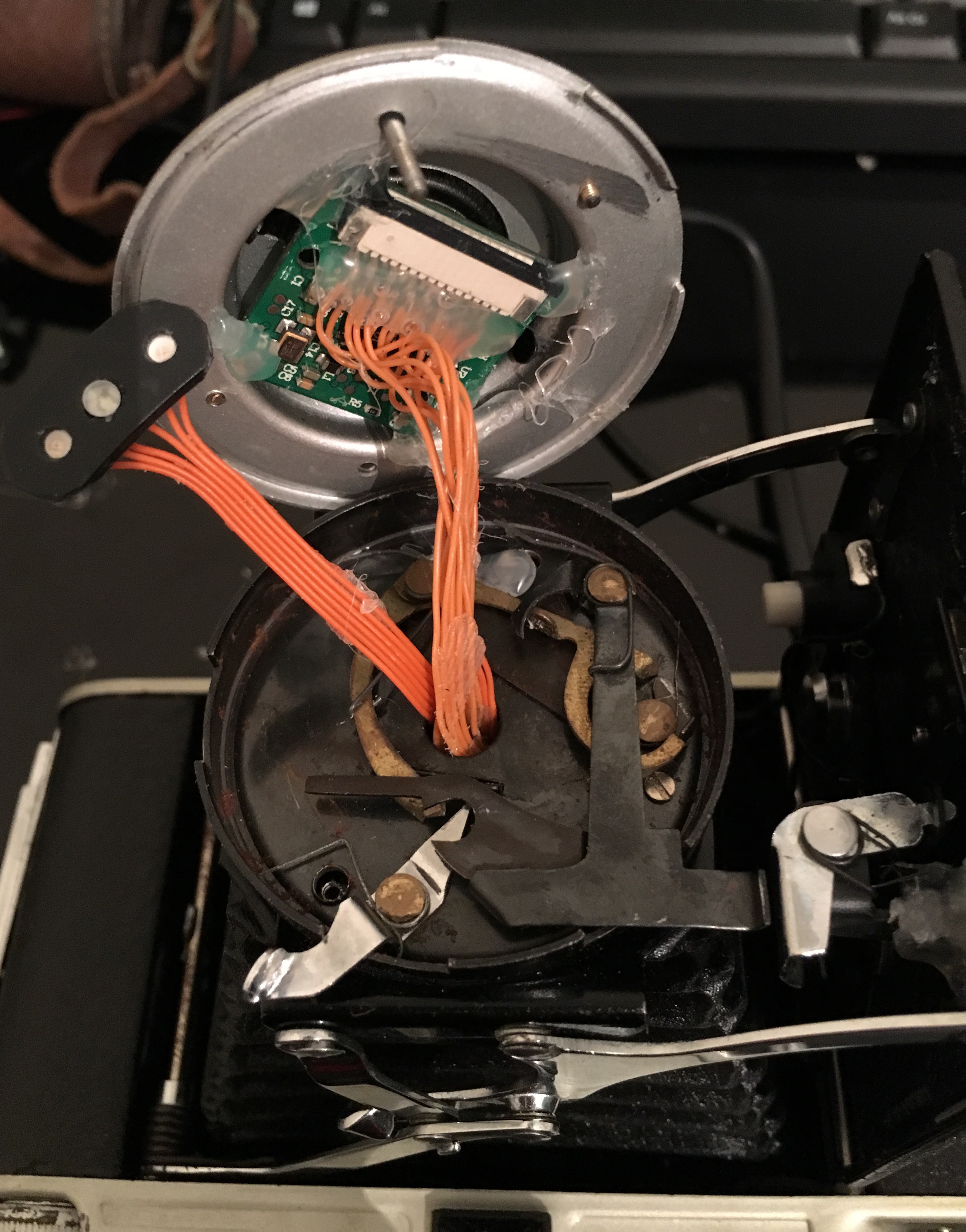
You might be wondering what the orange wires soldered to the camera module are for? Well, my original plan was to use the normal ribbon cable that is required to connect a camera to the Pi Zero but this was not long enough. I then tried the 30cm version of the ribbon cable and while this was long enough, it was not flexible enough to handle all the twists, turns and movement that would be required so I was forced to solder all 15 pins myself. This was simple enough at this end as the camera module has convenient solder pads for each of the pins (visible in the image below), but soldering the other end was a different story (more on that later)
The other part you may be wondering about is the black bean shaped thing with the 3 LEDS on it. This is my solution to the flash and status indicator problem. It is made up of two SMD LEDS, one green one blue, taken from an RGB LED strip I had an off-cut of and a flash LED in the middle. The flash LED was taken from an old iPhone 5c that had a failed mainboard so was otherwise useless.
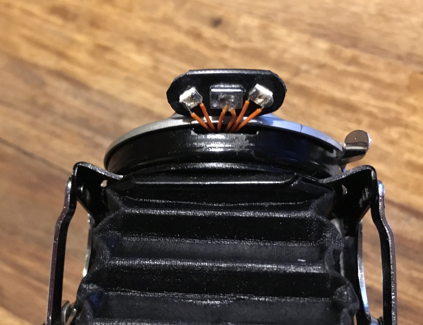
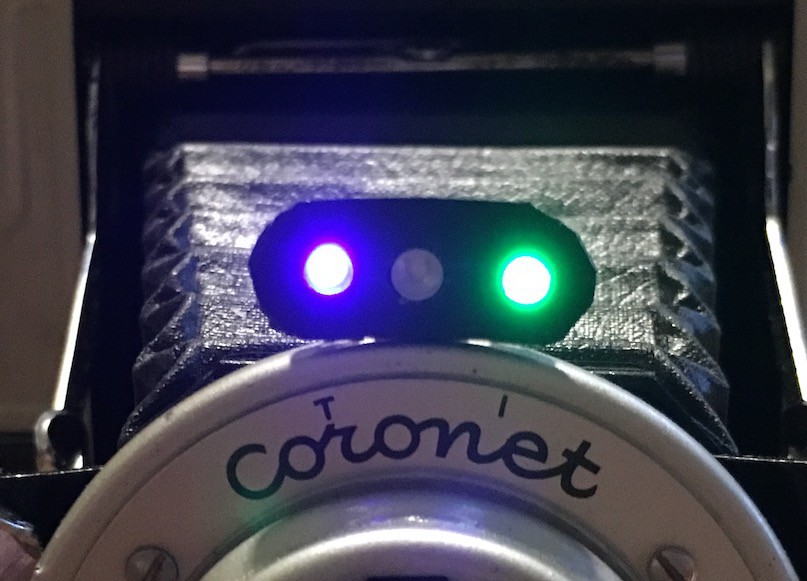 The cutting/shaping of the black plastic isn't as neat as I'd like, but it does the job. The blue LED is lit when the Pi has power (it runs of the constant 3.3v from the GPIO connector) and the green LED lights when the camera is ready (it is connected to a GPIO pin that is controlled in the python script)
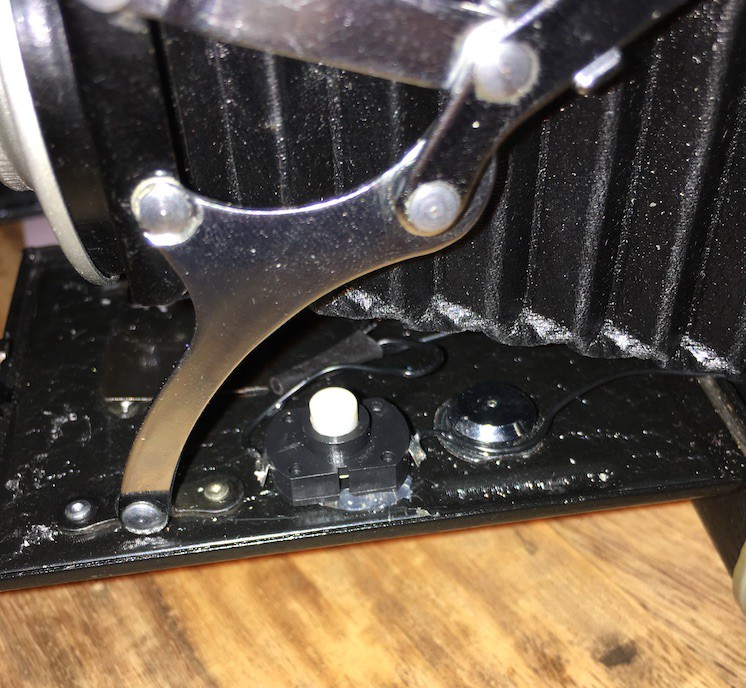
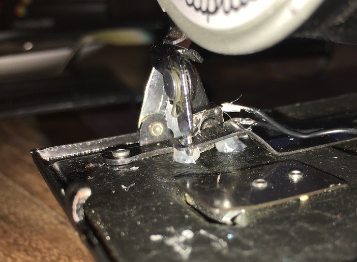
The Shutter Release Button
The camera has a manual shutter button which meant it was easy to insert a microswitch in the mechanism. This is connected to a GPIO pin on the Pi and means I can use the original shutter button to take a photo.
The Raspberry Pi (V3)
When the Pi Zero was announced I knew I was going to put one in a camera. 2 problems:
- The 2 versions did not have a camera connector
- I couldn't hold of one for love nor money
Thankfully, I managed to get one of the first batch of V3s and embarked on this project.
The recess on the opposite side to the battery compartment, where the film take up used to be, is 71mm by 26mm diameter. The dimensions of the Pi zero are 65mm (68mm including the mini SD card) by 30mm. This was going to be a tight fit.
Unfortunately I don't have any photos of the bare Pi and how it sits in the space but the finished arrangement is below
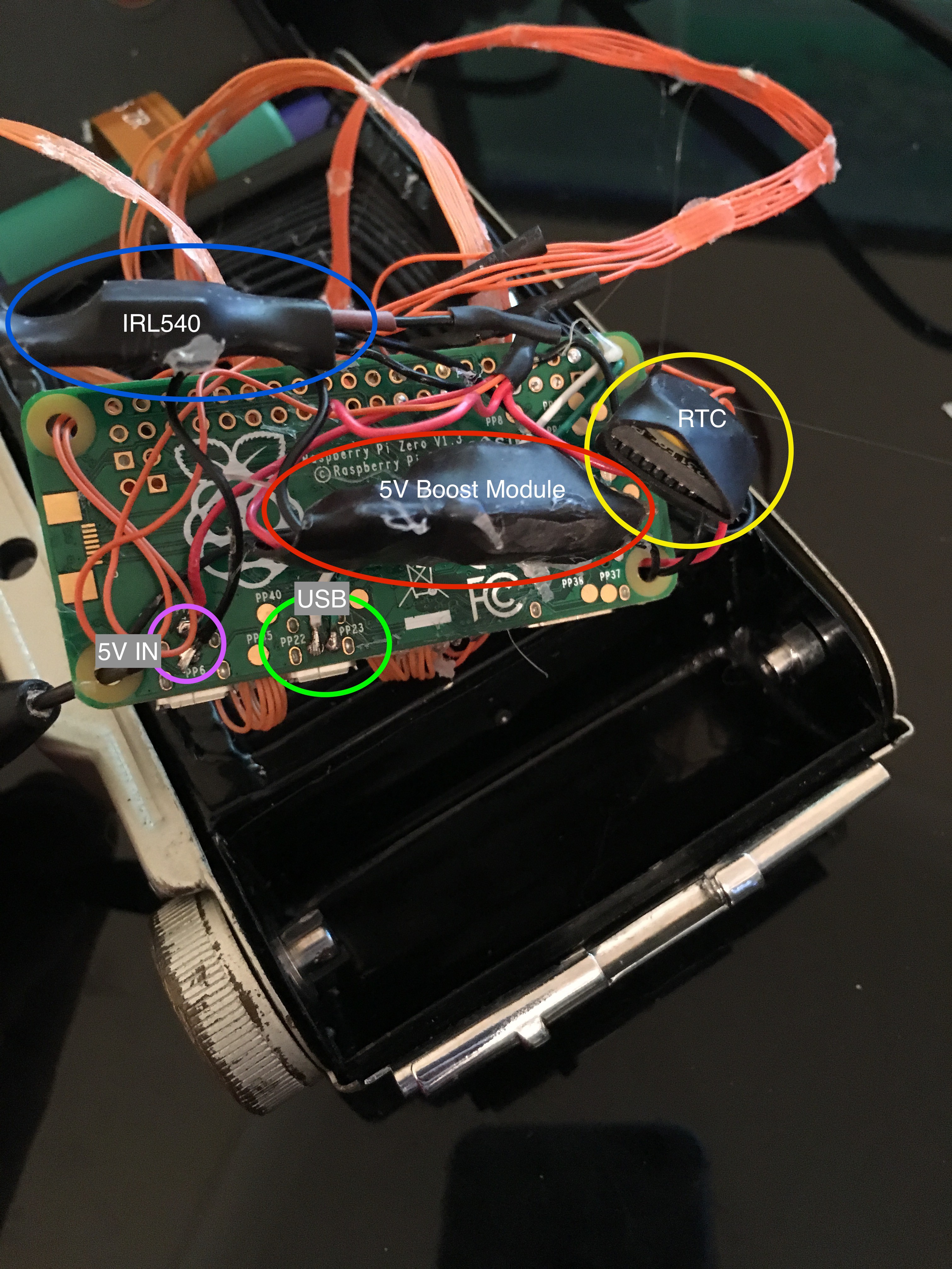
This tangle of wires comprises:
- IRL540 - This logic level MOSFET is able to switch a high current load, the flash, using a low current GPIO pin's output. This particular component is probably a bit overkill for what I ended up needing but better too good than not good enough. Plus I'd already soldered it.
- 5V IN - PP6 and PP1 are used to supply 5V to the board direct from the 5V boost module. No room for a micro USB plug.
- USB - PP22 and PP23 are used to tap into the USB data lines. These are taken to the other side of the board and connected to the WiFi/Bluetooth module
- 5V Boost Module - As mentioned above, takes the input from the LiPo cell which can be anywhere between 4.2v and around 3v and boosts it to the 5v required for the Pi.
- RTC - Real Time Clock. The Pi does not have any on board battery so cannot maintain the correct time while powered off. This can be set via NTP over the internet but as I won't have net access I'm using an RTC which communicates by I2C so is connected to the I2C pins on the Pi
These all bundle up and fit in the recess with the board on top
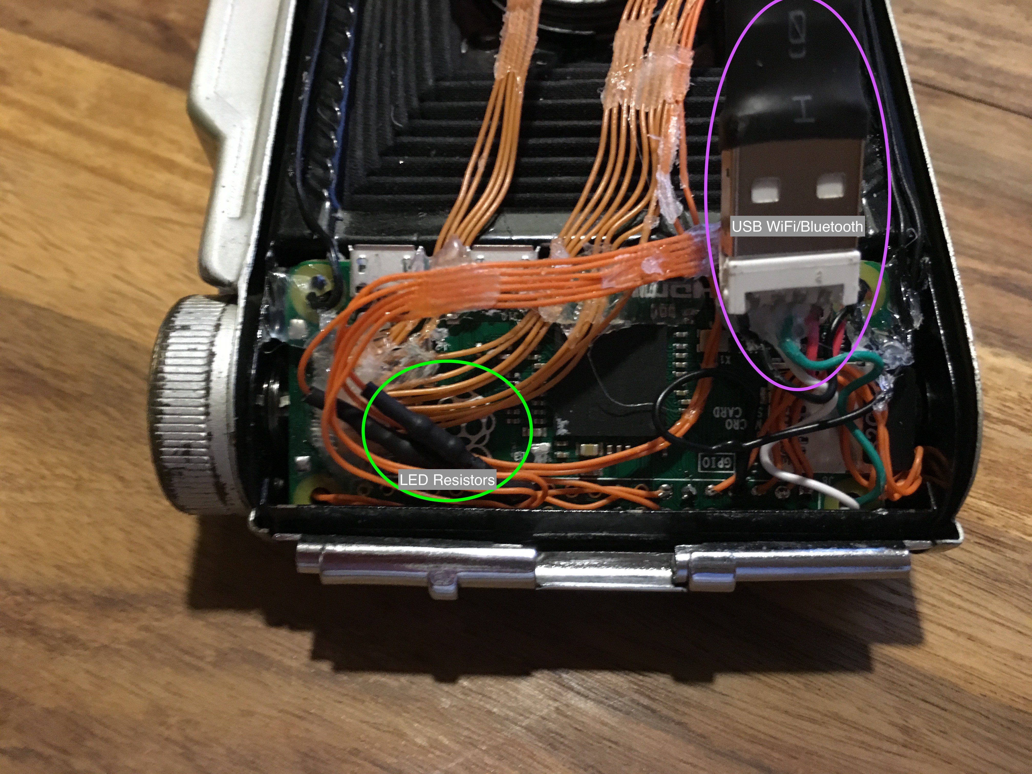
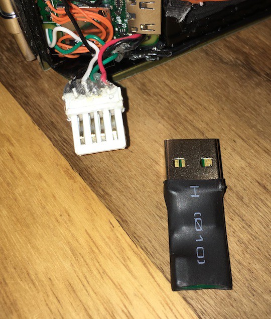
The above pictured shows the Pi wedged in the film compartment with the 5V booster, MOSFET and RTC hidden from view underneath. On this side we can see the current limiting resistors for the indicator LEDs along with the WiFi and Bluetooth USB dongle. As the USB port is wired directly to the Pi's SoC and not through a hub, we only have one port available. Therefore, without the space for a hub I needed a combined WiFi + Bluetooth adapter. There aren't many available but i went for this one and stripped it of its case.
The Pi Zero Camera Connector
Given the space constraints and the location of the connector, I could not use a ribbon cable to connect the camera module to the Pi Zero. When I tried, I had to bend the cable so much that it stopped working.
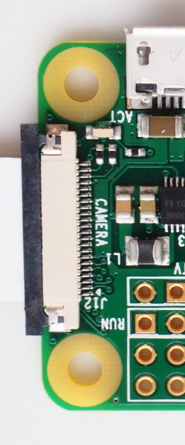
The minuscule connector above is on the opposite end of the board to the SD card which meant I couldn't cram a ribbon cable in to it. The solution? Remove the connector and solder wires directly to the connector pads!
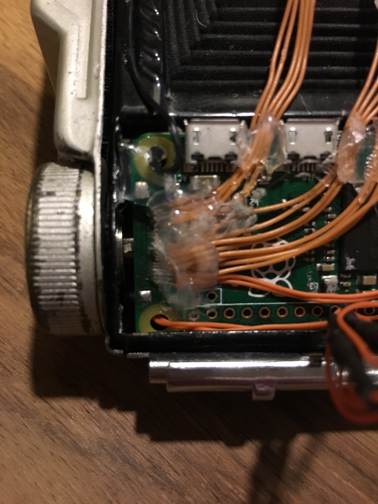
The connector pins are such fine pitch I thought I'd have no chance of it working first try. Happily I was wrong and the camera sprung to life on the first power on! A good dollop of hot glue to immobilise the connection and all was well. Or so I thought.
During testing/development of the software side of things, about half of the photos taken would have 'artefacts'. Half the photo green or purple, 'static' horizontal lines etc. I had a suspicion this was down to crosstalk as I had just arranged the cables in one big bunch rather than in the same order they are on the ribbon connector. Thanks to Peter Vis and his CSI pinout list, I was able to identify the important channels and bunch them together in improvised ribbon cables (hot glue - yay!).
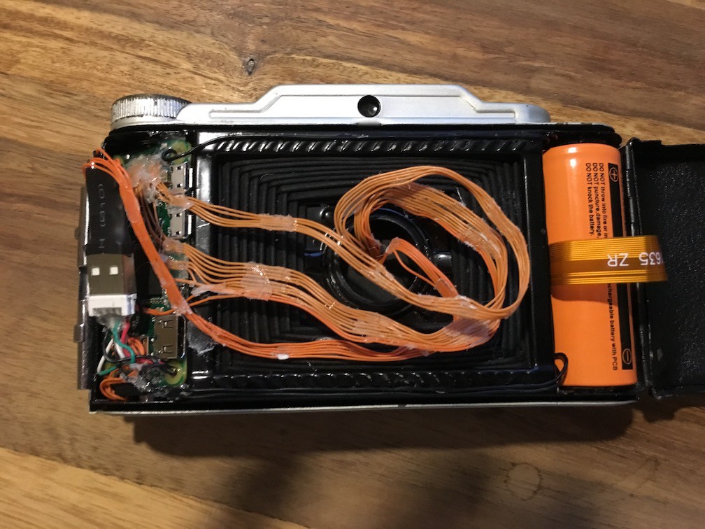
These are arranged as they are in a kind of spiral to allow for expansion when the bellows are opened.
And finally, video of it in action (sorry about the vertical video, I'll do better next time).
Discussions
Become a Hackaday.io Member
Create an account to leave a comment. Already have an account? Log In.