• Introduction + First Look at PCB

    Arno Moonen01/20/2017 at 21:44 0 comments

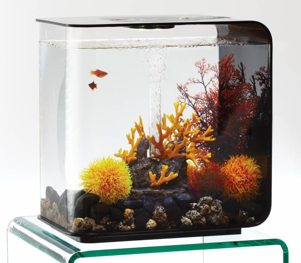
    Recently we bought a BiOrb Flow 15L aquarium for our two fish. It looks pretty sleek (as you can see in the picture that I grabbed from the internet) and has a built-in filter and white LED light, both powered from a single AC-AC adapter (that has two 12VAC outputs: one for the air pump and one for the LED light). Almost immediately after our fish were settled, I was kind of annoyed by the fact that I can control all the lights in my living room from my smartphone, except for the light in the aquarium.

    The first solution I thought of was using a simple RC switch, however, this would also turn off the air pump, which I did not want. By default the LED light is switched by a mechanic switch that simply cuts one of the two 12VAC lines. I figured I could just cut open the cable and put a relay in between that was controlled via some microcontroller that I could hook up to HomeBridge.

    I even got my girlfriend excited (I think), except for the part where I wanted to cut the cable. Fortunately, the adapter has two female "retro loudspeaker" connectors (later on I figured out these were called DIN-41529). After a lot of searching I managed to find a female and male connectors, so I can simply add a cable in between the adapter and the LED light. Those connectors are pretty expensive, but if it makes my girlfriend happy, I guess, it's worth it.

    Very soon after that I started designing a PCB, mostly based on components I had left over from previous projects and ordered these from Elecrow. They arrived last week (all in all it took less than two weeks... pretty fast!) and they look very nice.

    Top of the PCBBottom of the PCB

    As you can probably tell from the pictures above, I decided to put all the components on the same side. This is because I recently ordered a hot plate to solder components using a reflow process. This will be the first project I will try it on.

    You are probably wondering what kind of components will go on to the PCB. Well, on the left side of the PCB (where the cut outs are and the fish is drawn), there will be two screw terminals (power in / out) and a dual coil latching relay (HFD2/003-S-L2). For each of the coils of the relay, there is a 1N4148 diode, a MMBT2222 transistor and some resistors.

    The power in is also connected to a bridge rectifier (MB6S), which goes to a well-known AMS1117 3.3V power regulator (with some capacitors and quite a large piece of copper on the PCB as a "heatsink").

    The brains of the operation will be an ESP8266 (ESP-12 module). Besides driving the coils of the relay, it will also blink a 3mm status LED (via a transistor) and respond to a press on the tactile button. This (right angle) button is located on the right end side (with an RC filter for debouncing).

    Furthermore, you will also see some pin headers. These are meant for programming and resetting the ESP module.

    Here you can see the board with some of the components placed on it (not yet soldered, just verifying the footprints) and the case I had in mind for this project. Unfortunately, the seller of this SZOMK AK-N-01 case, sent me an incomplete drawing of the case. I appear to have used to wrong measurements (since there weren't any other in the drawing) to determine the location of the mounting holes, so the mounting holes are way off. Plenty of ways to work around that 'though.

    In my next post I'll give you an introduction/update regarding the software side of this project. Once I have finished the project successfully, I'll be sure to share some/all of my work with you.

    Thanks for reading!