-
PCB changes
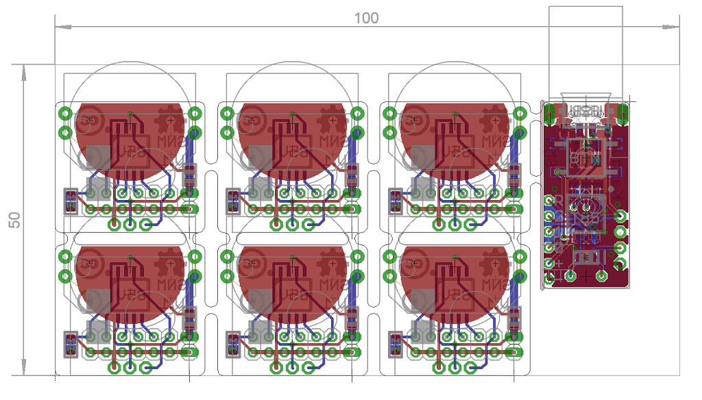
11/18/2014 at 17:31 • 0 commentsIt turns out Elecrow has some trouble manufacturing half-holes which I used for the CR2032 battery holder in order to save some space. It doesn't really matter so I made the half-holes whole and since I had to make the transmitter board bigger I also broke out the RF signal pin and LED so that they could be used if the module was used in a different way.
![]()
As you can see the board still fits the 5x10cm limits.
-
PCBs
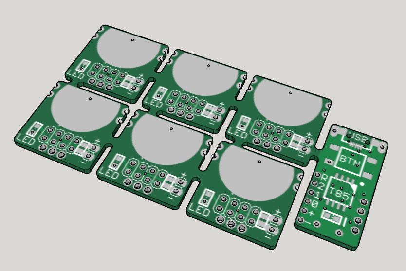
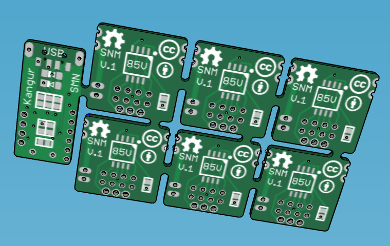
11/17/2014 at 18:21 • 0 commentsI made the PCBs in Eagle CAD and ordered them from Elecrow as they currently a have a 5x10cm board size special offer, it remains to be seen if they actually agree producing them as there are some particularities with panelized PCBs.
![]()
![]()
The 3D rendering was made using EagleUp, a plugin for Eagle CAD and SketchUp, all free.
I put 6 transmitters and one receiver on the board, I plan to use the other transmitters to report on various variables around the house such as temperature (with the internal temperature sensors which I'll calibrate for each MCU separately) and it can also be hooked to other systems (heating, power consumption, water usage...) which all report to the central receiver that can then dispatch the information wherever needed. It remains a one way communication, but a very cheap and power efficient one.
I also added a coin cell battery (3V) holder footprint on the receivers as I want those transmitter to be as small and self-contained as possible, I hope the transmitter current draw isn't too high and those cells have quite a high internal resistance. I added to 10uF capacitor on the line, it's probably not enough but it's something.
-
Huge leap
11/14/2014 at 17:38 • 0 commentsI haven't updated this project for a long time, but that's because I've worked on it on the side whenever I had time and changed my mind a lot.
It has taken a bit of a turn: I have discovered V-USB/Digispark on the way and decided the receiver should be a stand-alone module as my receiver-connected-to-a-random-Arduino wasn't as elegant as I hoped. I bought some ATtiny85-20 and other passive parts to test them on a custom etched a circuit. I now have a fully functional USB receiver module that forwards data to a computer.
![]()
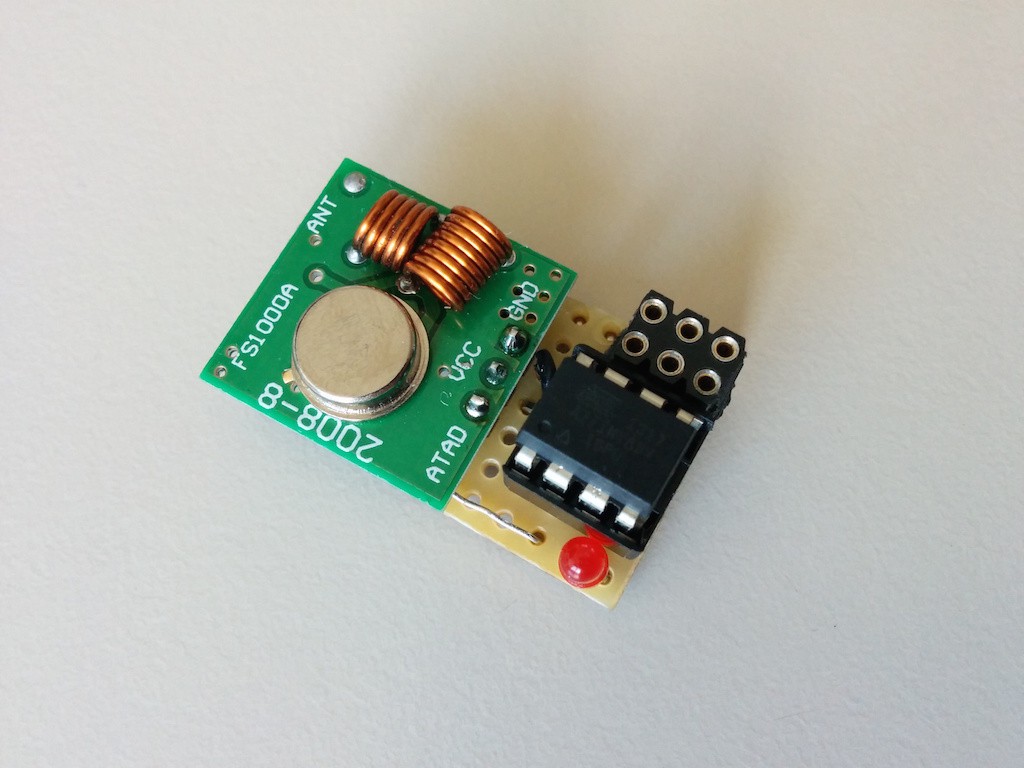
Early transmitter module on a stripboard with a DIP ATtiny85V-10 MCU.
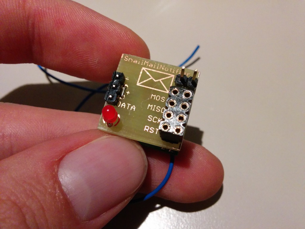
![]()
![]()
Current transmitter module on an etched PCB, the MCU can be reprogrammed via the broken out pins.
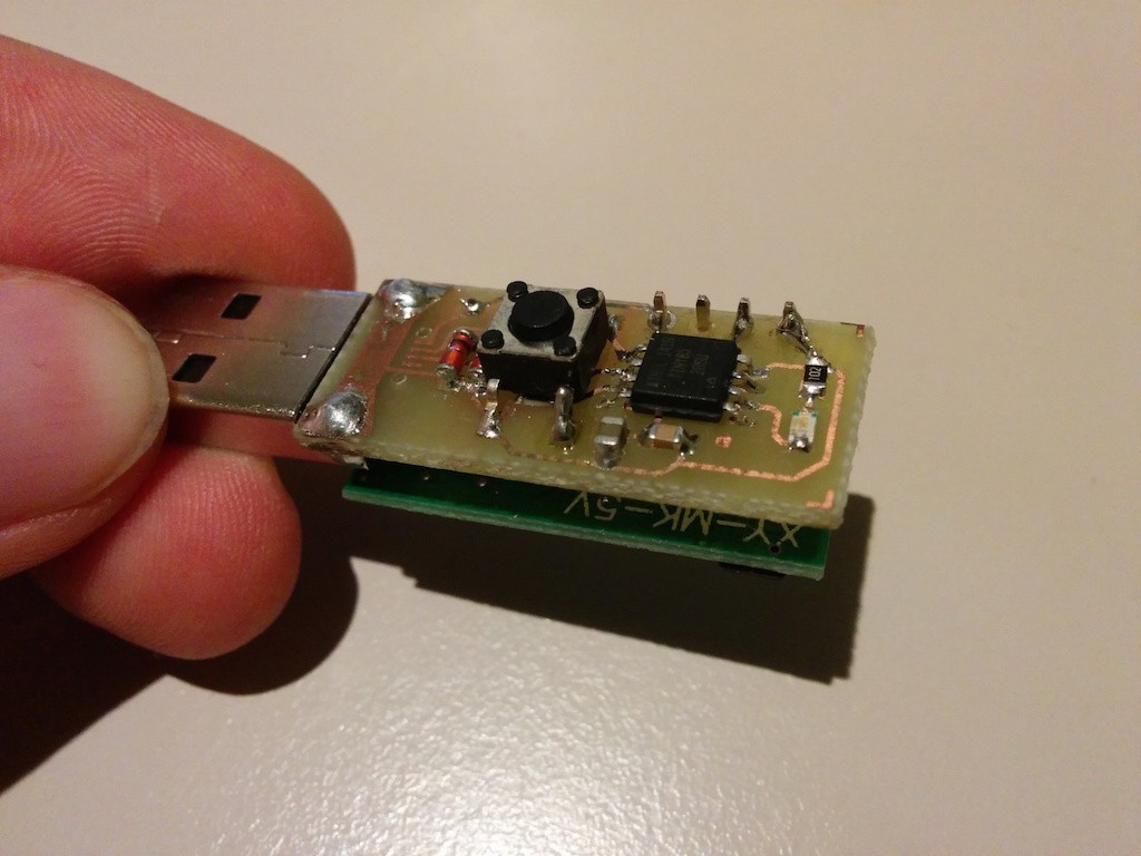
![]()
Receiver module with both USB-A and micro-USB connector footprints. I programmed the MCU via a temporarily soldered ISP connector, now it can be reprogrammed using the Digispark bootloader.
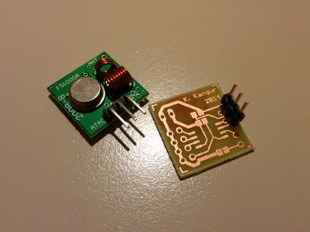
I will definately be using the cheap 433MHz transmitter/emitter pair mainly because of price, low power usage and virtually no voltage regulation requirements. The transmission is quite reliable.
Something that is a bit annoying currently is that I use a ATtiny85V-10 for the transmitter and an ATtiny85-20 for the receiver (because of USB), indeed the 85V version can function down to 1.8V, but I'm not sure it's really useful as I intend to power the transmitter via a 3V lithium button cell and also the transmission power being dependant on voltage this 1.8V "advantage" might make it absolutely useless.
I have measured the power consumption of the transmitter and it was only 100nA in power-down mode, also thanks to the transmitter module that doesn't consume any power whatsoever, contrary to NRF or RFM modules. The ATtiny85V-10 can work at 1MHz between 1.8 and 2.4V and up to 8MHz from 2.4 to 5V, when I tested it I could get reliable transmission with 8MHz at 1.7V, completely out of specifications :).
As far as software is concerned both modules work as expected: transmission, reception and forwarding to computer. The Atmel MCU can measure their own supply voltage and have an uncalibrated internal temperature sensor which I forward together with the actual data just because I can.
I'm about to order some PCBs for both sides to make the whole thing more elegant and professional looking. By the end of the project both sides will have a nice 3D printed enclosures.
-
Another similar project
07/20/2014 at 11:00 • 0 commentsEric Tsai made a similar project using an Arduino compatible MCU, he's using the RFM69HW wireless module for data transmission, just like the Moteino, it might be a better idea than the NRF24L01, but more expensive...
As far as the sensor for detecting new mail delivery is concerned my first idea was a light sensor to detect the mailbox opening (while the module is inside the mailbox), but I figured since power consumption must be minimised the sensor should be a passive one. So I'll just use a button based "sensor" that'll trigger an interrupt and wake up the MCU, this way the "sensor" won't draw any power whatsoever while waiting.
-
First steps...
07/18/2014 at 08:40 • 0 commentsThe first step in this project is to build a test rig, a good start is choosing the hardware for the transmitter/receiver and MCU is to look at existing projects. I bought a couple of popular NRF24L01 wireless modules to test the range, later I'd use the SMD variant if the tests prove satisfactory for mounting on the PCB.
As far as the MCU is concerned I'm most confortable with AVR chips and I already have developing tools for it (USBasp programmer) so I'm leaning towards that. I know that the AVR MCUs are quite stable within a large input voltage range which is perfect for this kind of battery powered project, for example some of the ATtiny MCU can be powered with only 0.7V. They also have low power consumption mode theoretically allowing them to run for absurd amounts of time (years) on standard batteries.
Ideally no regulator has to be used, the NRF24L01 seems to run happily from 1.9 to 3.6V, but once the transmitter starts sending data it draws a lot of current from what I've read, an important voltage drop might cause problems when a battery with a high internal resistance is used (such as a coin battery), to be tested...
I'm now waiting for the delivery of the electronic components to start building the test rig. The first test is to check the transmitter/receiver range and if it can communicate between my mailbox/house.
Snail Mail Notifier
Low power, wireless device that informs user of regular mail.