Here is a schematic of the circuit I plan to use:
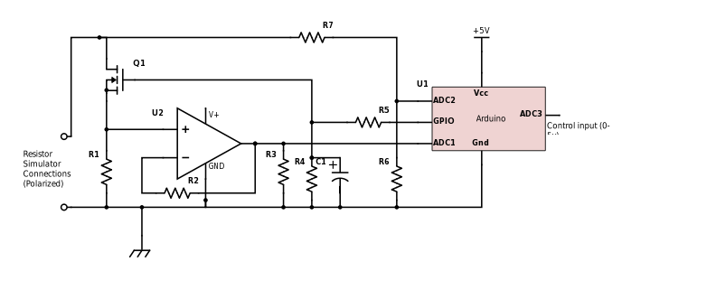
R1 is the current sense resistor. It will probably be around 0.1 ohms, giving 10mV at 100ma. U2 is a opamp with the gain set by R2 and R3 to bring that voltage up to the range for the ADC. The voltage across the simulated resistor goes into ADC2 through a voltage divider designed to support up to 15 volts across the "resistor". The current through the "resistor" is controlled by a GPIO pin with simple "bang bang" control. It drives the gate of a MOSFET via a current limiting resistor/ low pass filter comprising R5 and C1. R4 is for gate protection, say 1 megohm. The time constant for C1 R5 is set to about 1 second as fast response is not required. This also biases the MOSFET into its linear region where it will act like a somewhat non-linear voltage controlled resistor on its own. Operating the MOSFET in its linear region increases its dissipation but at less that 100ma at less than 12 volts, this should be less than 1.5 watts which is easily handled by any decent power MOSFET without a heatsink.
Right now, I am deciding on what MOSFET to use. It must fully turn on at less than 5 volts, have the lowest possible gate threshold voltage and an on resistance of no more than a couple of hundred milliohms. I will probably use a AO518 as I have a lot of them.
The code is in two parts. One takes the control input from ADC3 to set the "resistor" value. This will use a small lookup table with interpolation to provide first order correction for non-linearity. The second part maintains the effective resistance by providing closed loop control of the ratio between the current sense voltage and the overall "resistor" voltage. I was thinking of using a PWM output with PID control but as it is OK for the response time to be slow in this application, simple on/off control with the low pass filter should work well.
Although the circuit as specified uses an Arduino mini-pro with a separate opamp, I am tempted to use a Cypress 4200 PSOC chip as they can be set up to handle both the analog part and the digital part on the one chip. It is somewhat overkill, but simple dev boards are available for $4 so it is certainly cheap enough.
Discussions
Become a Hackaday.io Member
Create an account to leave a comment. Already have an account? Log In.