 Simon Trendel
We are a student team from Munich, Germany. Our goal is to make Roboy balance and walk. For this we need accurate tracking. We decided to replicate HTC lighthouse tracking for our purposes and in November 2016 a fascinating journey began.
Checkout this excellent review on the HTC lighthouse tracking system.
At first we tried decoding the signals from the sensors using Intel Edison and MKR1000, which in case of the Edison turned out to be impossible and in case of the MKR was limited to a small amount of sensors. For the Edison the hardware interrupts were not handled fast enough. This is due to a threaded interrupt system. We also tried using the MCU, which wasn't fit for the job eaither.
The MKR was simply overwhelmed by all the interrupts.
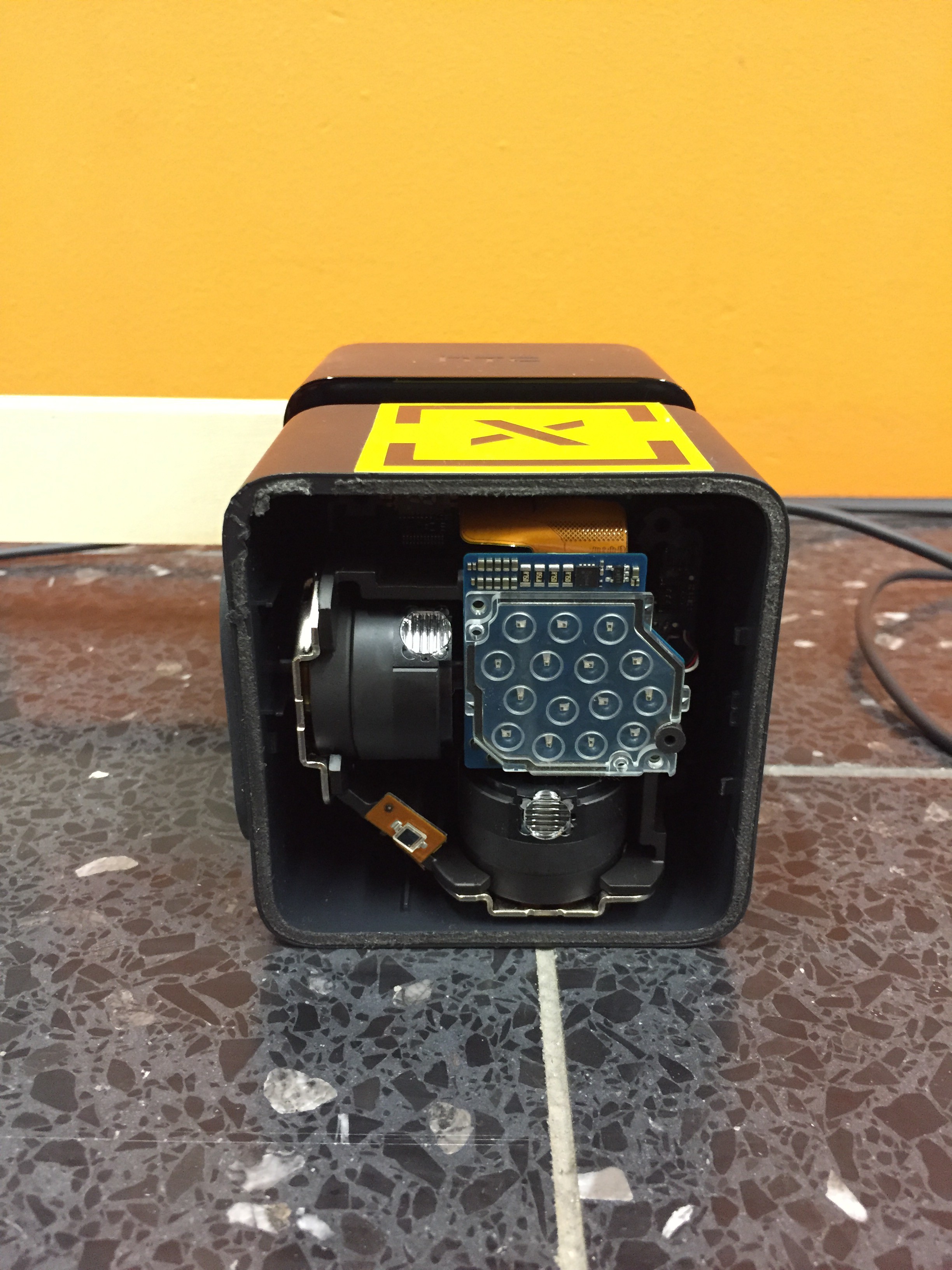
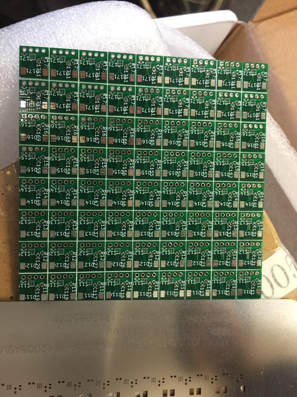
We disassembled one of the HTC vive controllers for getting our hands on those sensors. We noticed the HTC controllers were using an ICE fgpa. So we thought if they use it, there must be a reason.
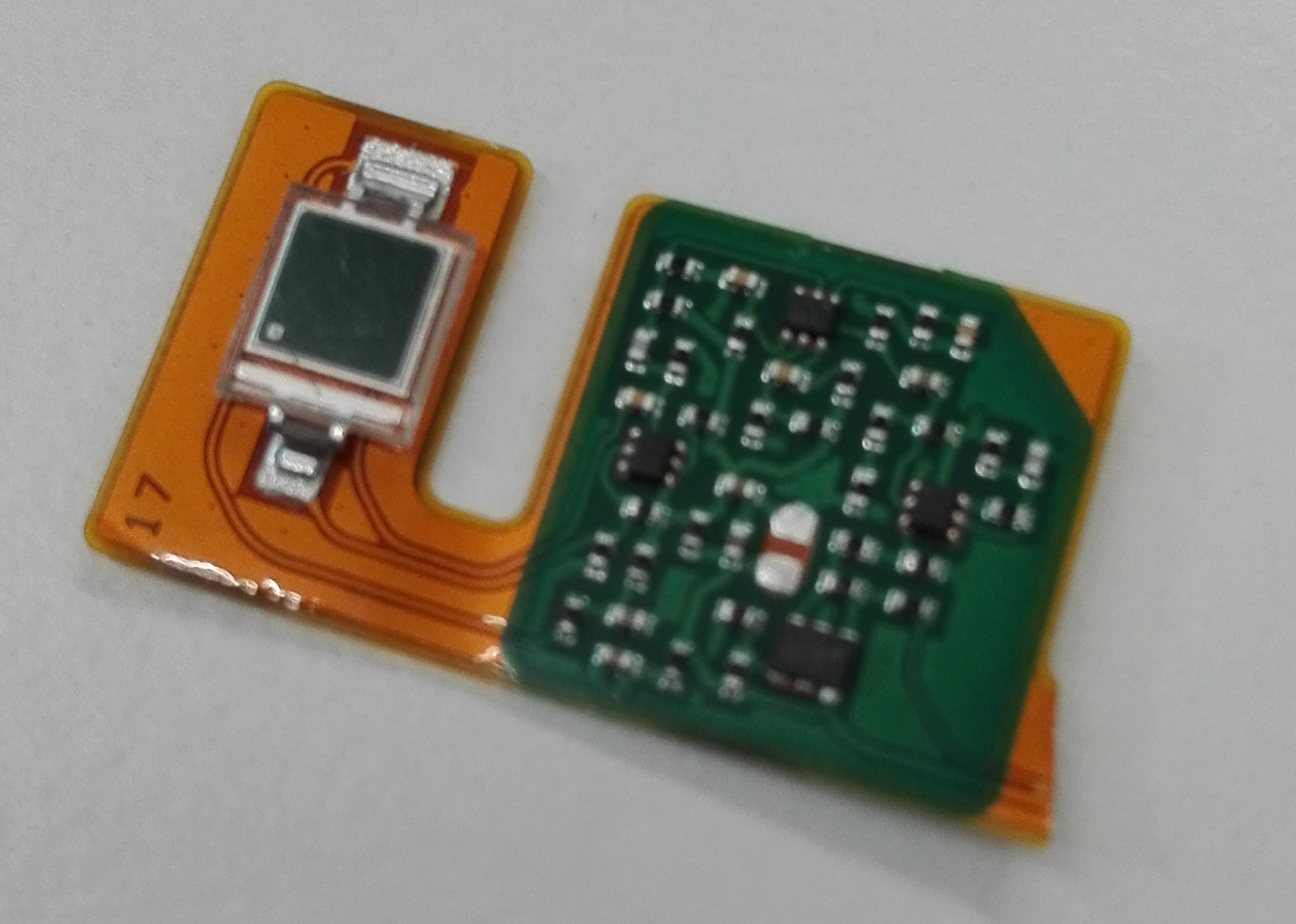
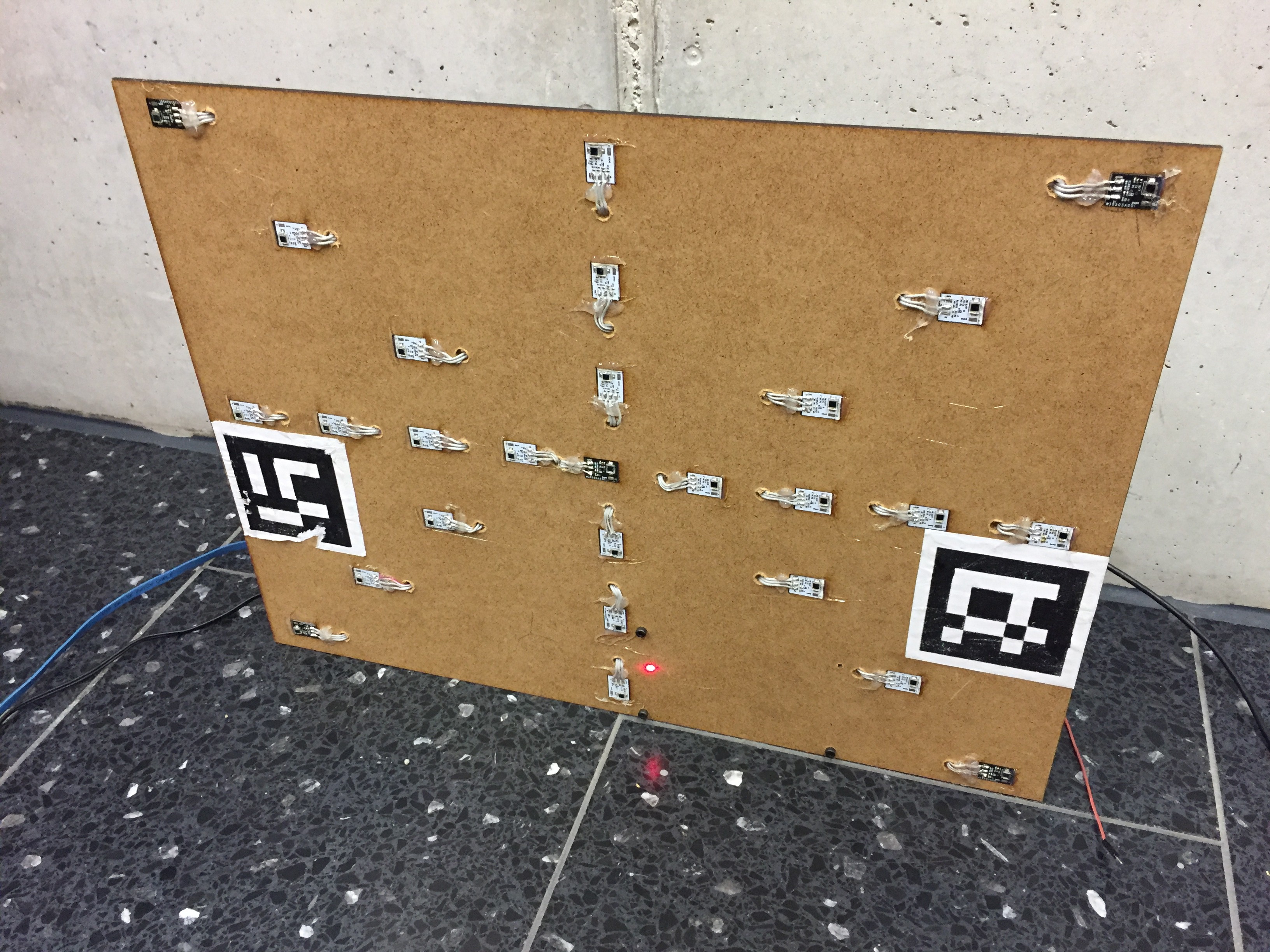
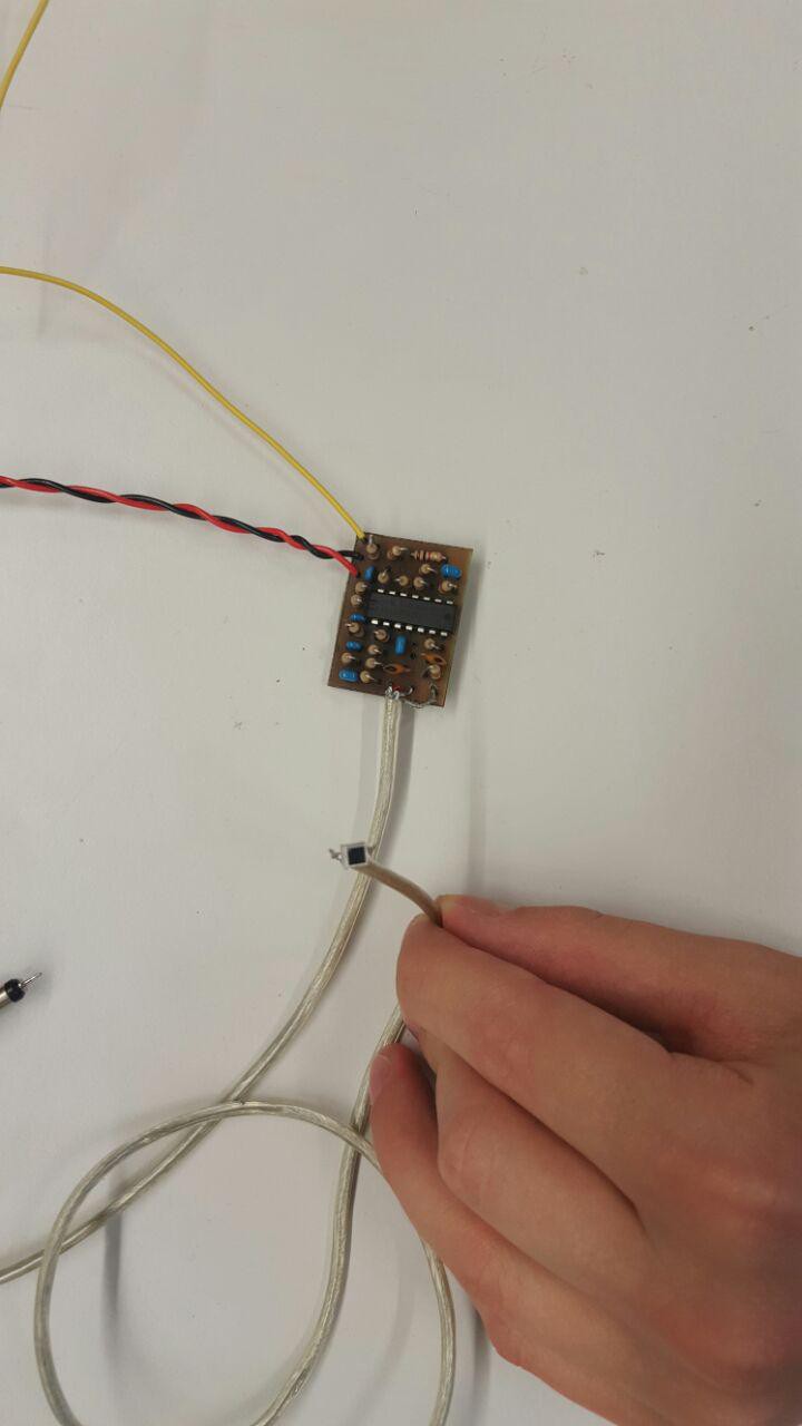
Then soldered VCC, GND and Signal copper cables (0.1 mm), using enough flux. And covert the sensor with a bit of glue to protect it from accidental damage.

In the previous prototype we were routing all signal cables coming from the sensors in parallel. This turned out to be a bad idea. Because of induction the signals pollute each other. In the vive controller, they deal with it by isolating the signal with VCC and GND. So thats what we are also doing.
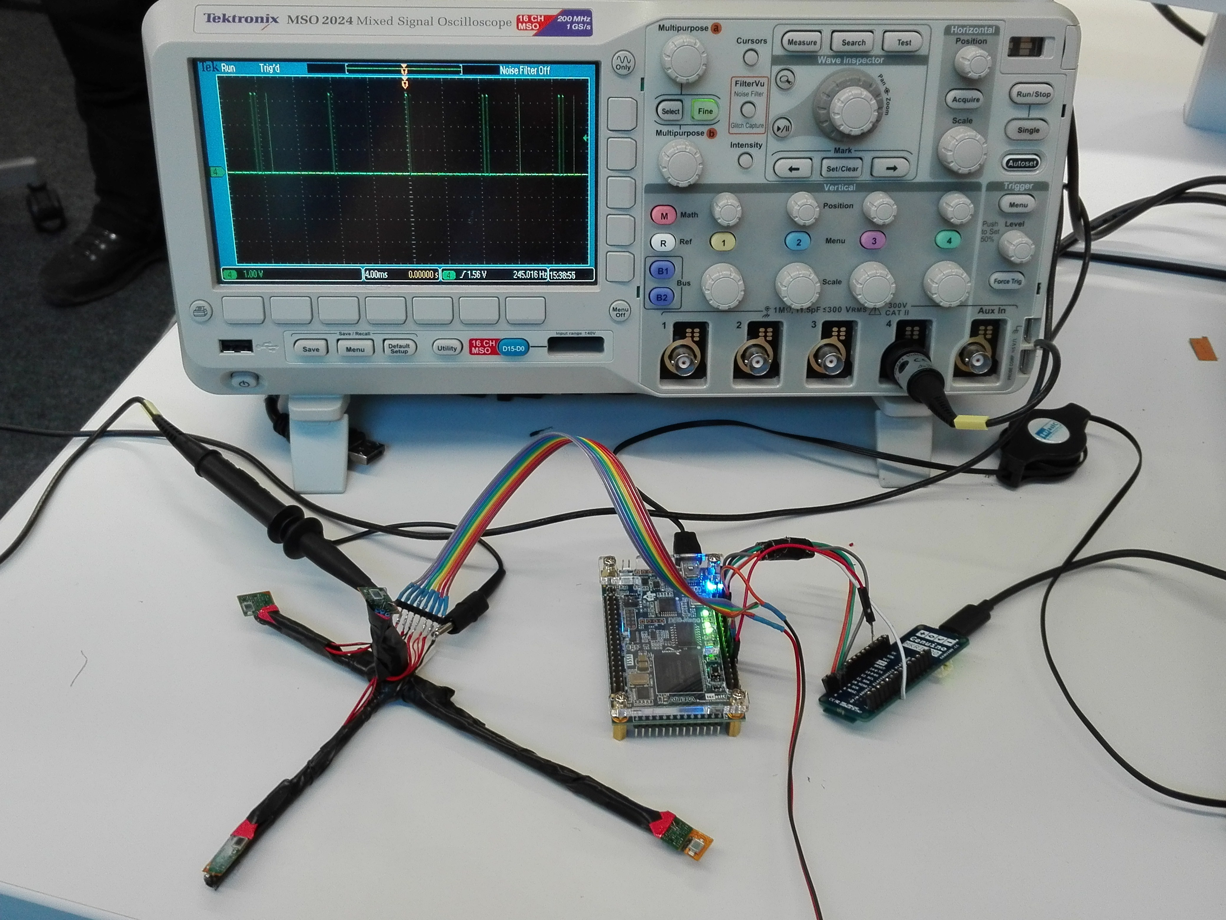
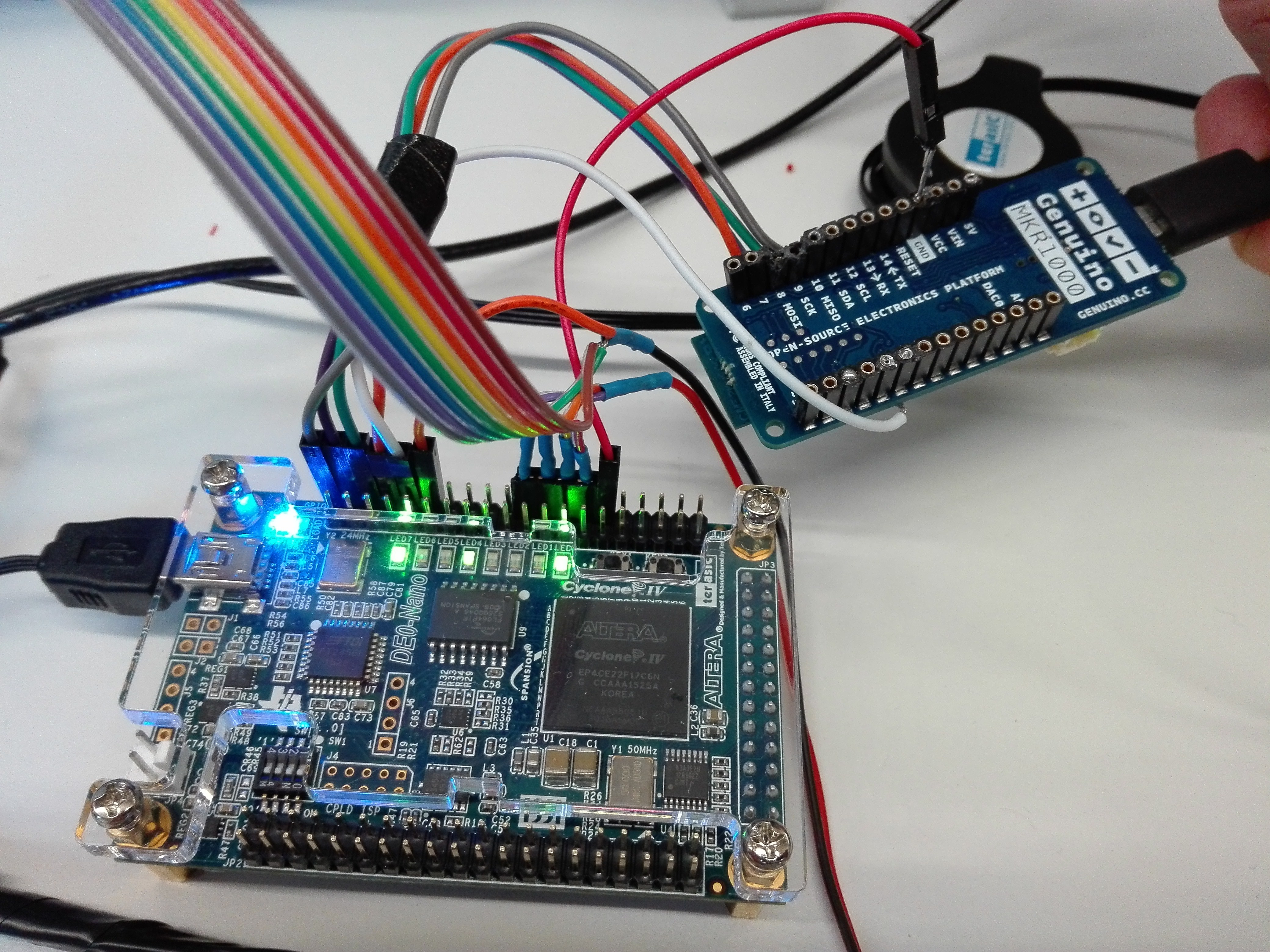
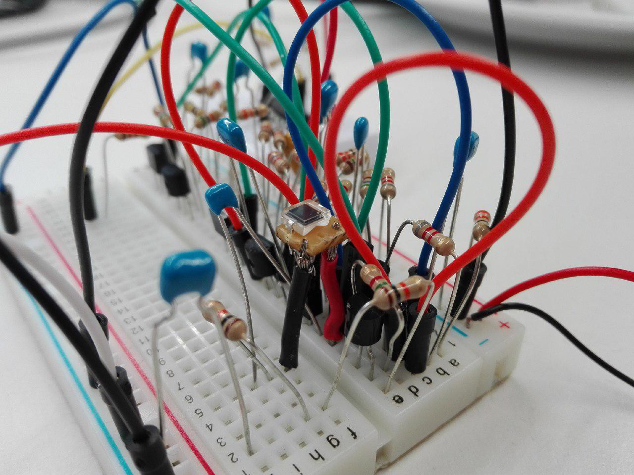
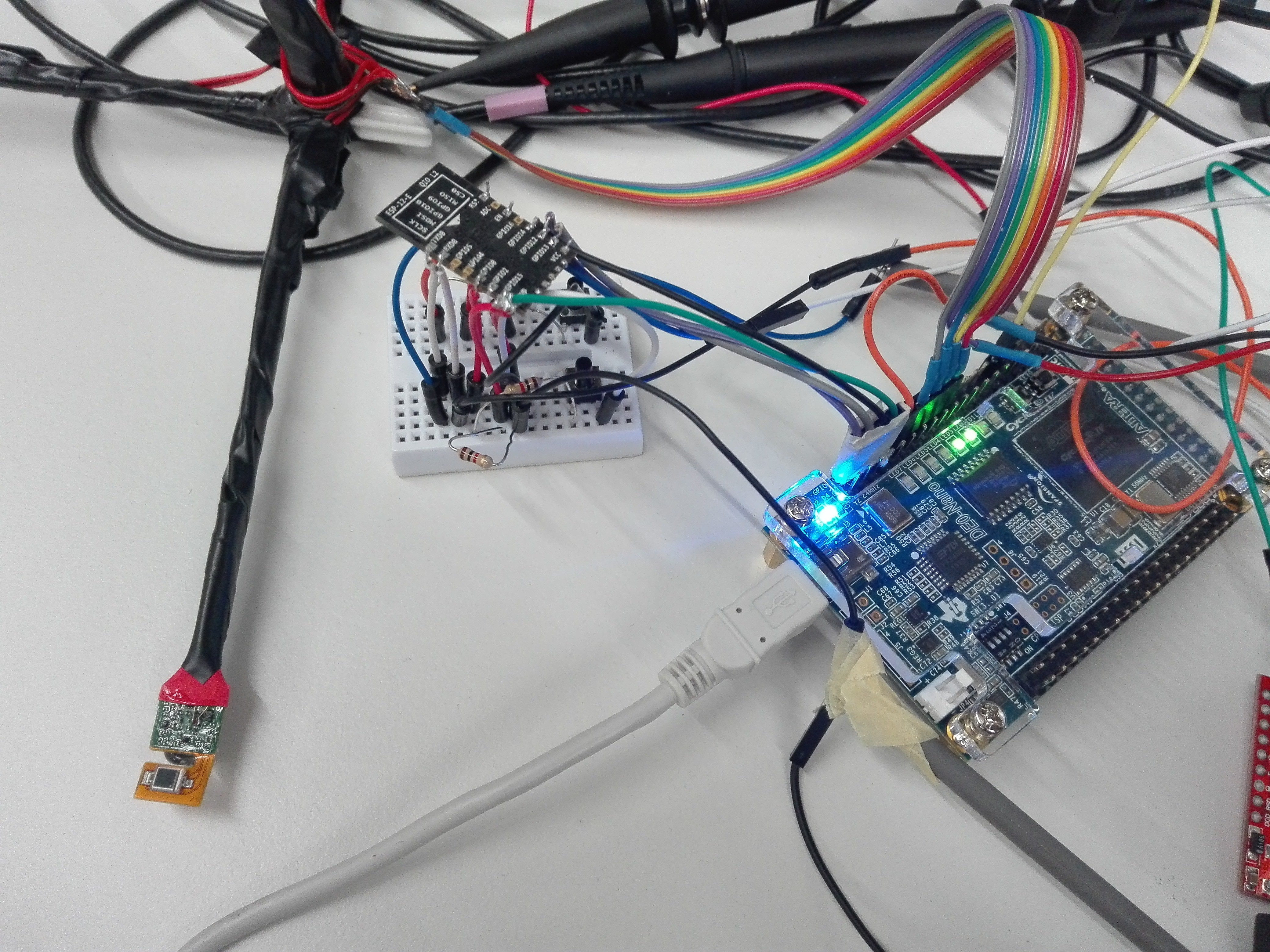
In the following picture you can see the complete setup:
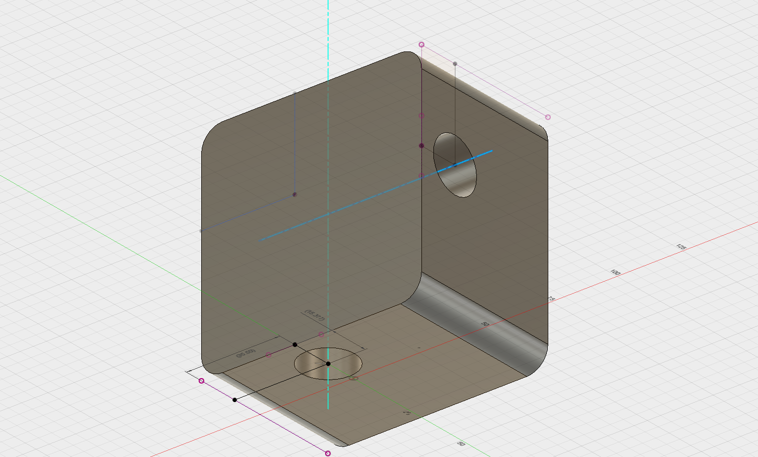
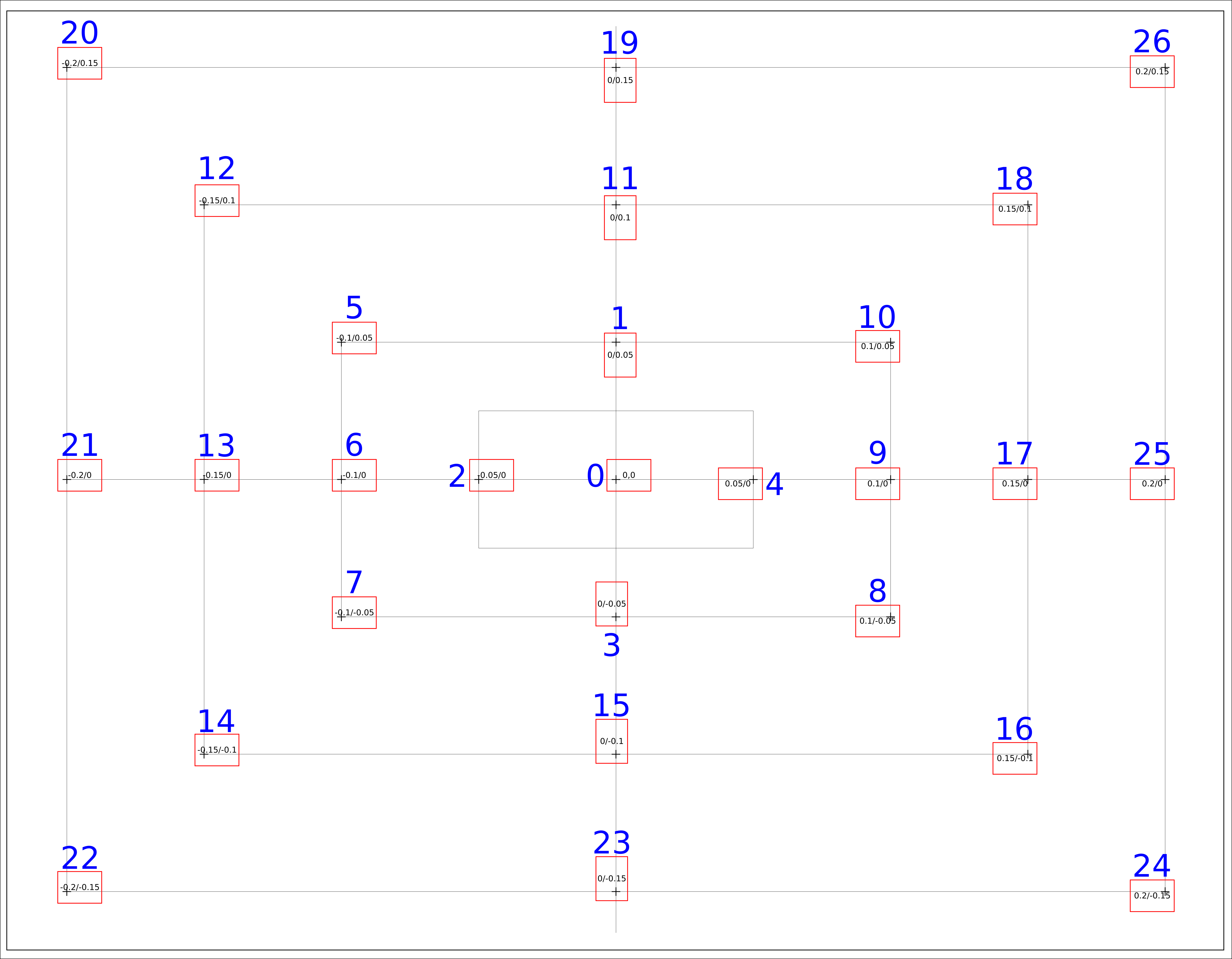
- The custom object, with 4 sensors
- The de0 nano FPGA
- The MKR1000
[Note: This is the old setup. New updated setup is described in section 7.]
Notice that there are only 4 sensor signal cabels (grey, blue, yellow, red). The other cables are VCC (purple, orange) and GND (green, brown).
The connection to the MKR is via SPI, where the MKR acts as the Master. An additional pin to the MKR notifies the MKR, when there is new data available. This triggers the SPI transfer.
Our vive tracking consists of a couple of modules:
- Decoding the sensor signals and calculating the sweep durations (this is done on the fpga)
- Transmitting the sensor values via SPI to the MKR1000
- Transmitting the sensor values wirelessly via UDP to the host
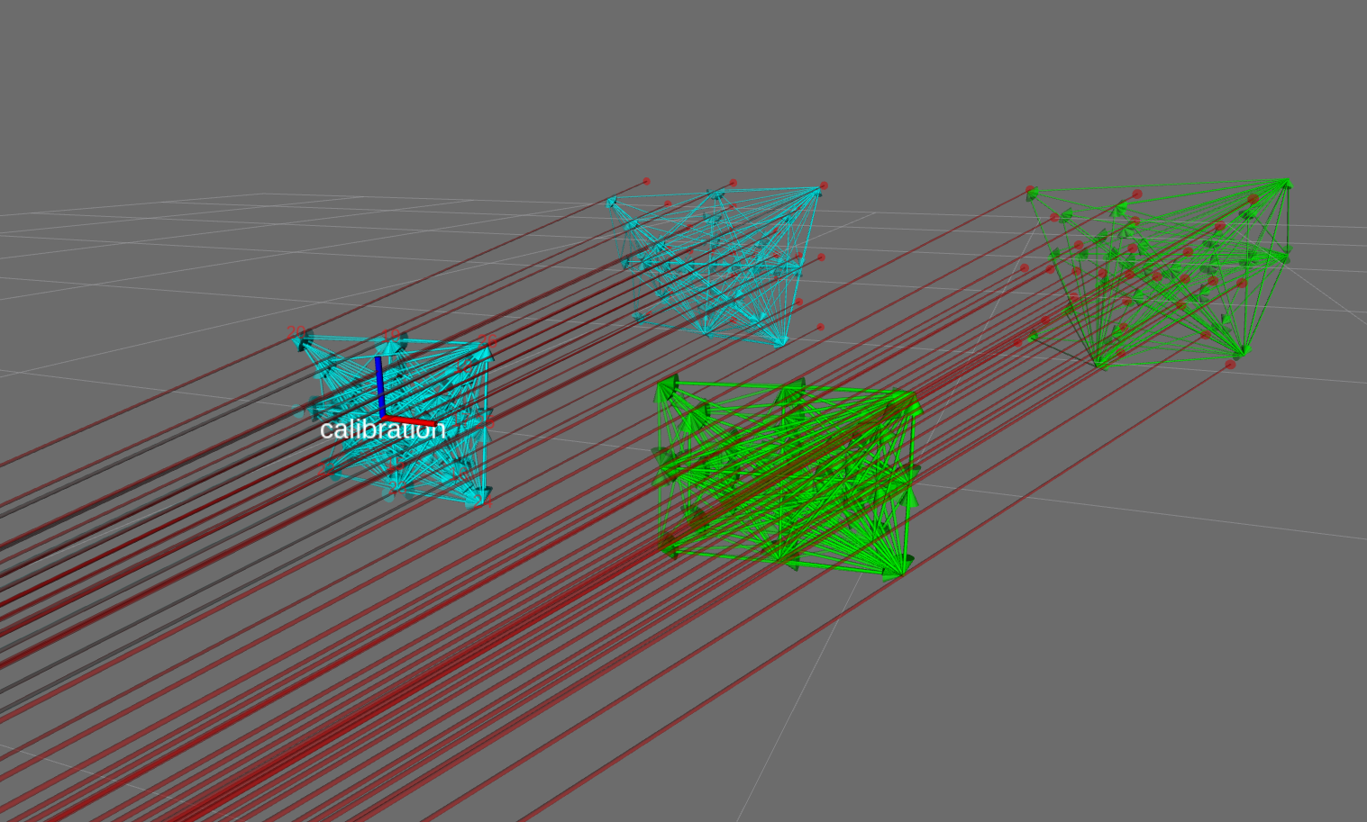
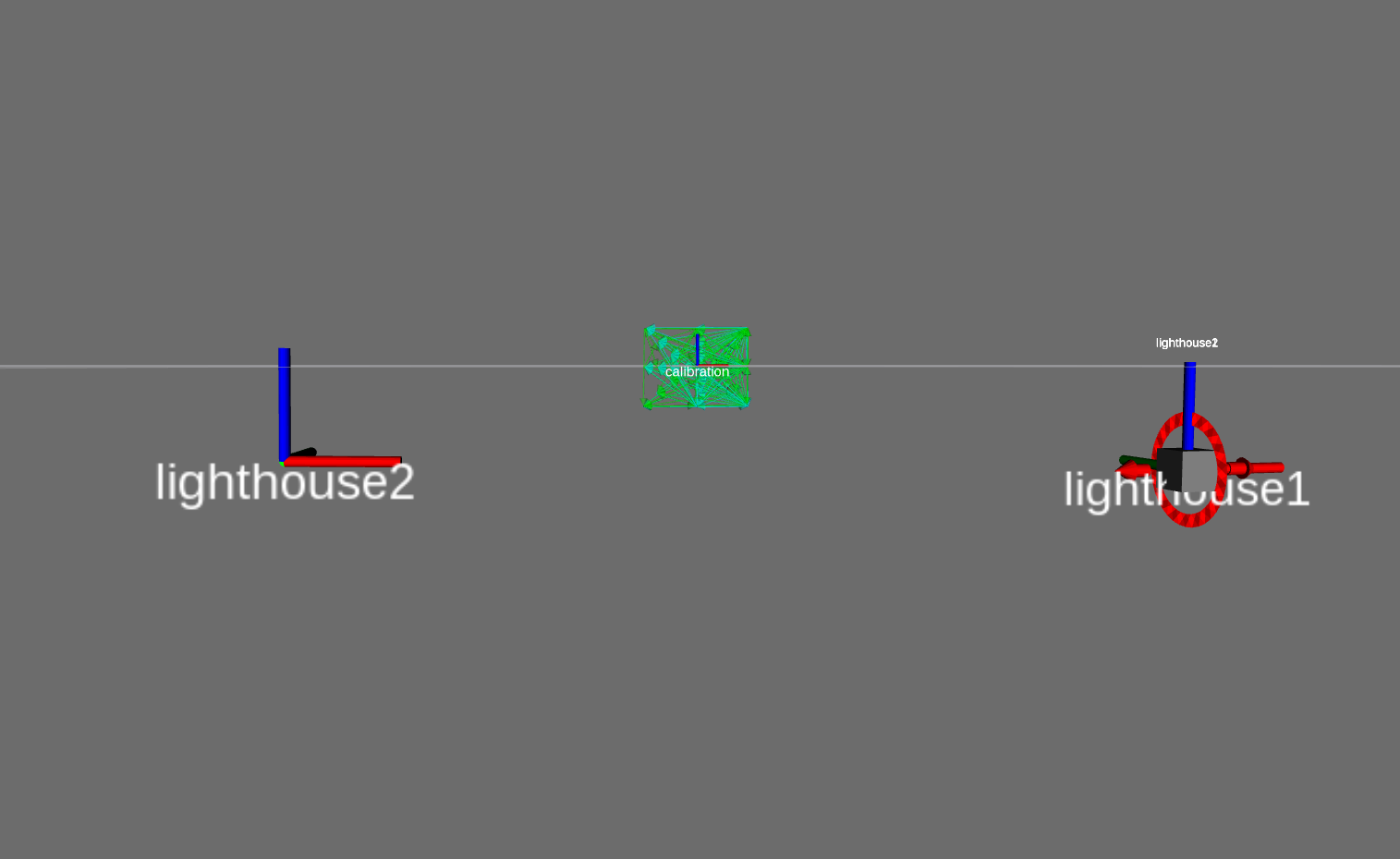
- Triangulation of the ligthhouse rays
- Distance Estimation wrt a calibrated object
- Relative Pose correction using a calibrated object
1. Decoding sensor signals
[Note: This is the old decoder. New updated decoder is described in section 7.]
On the de0 we are using a PLL to get a 1MHz (1us) clock
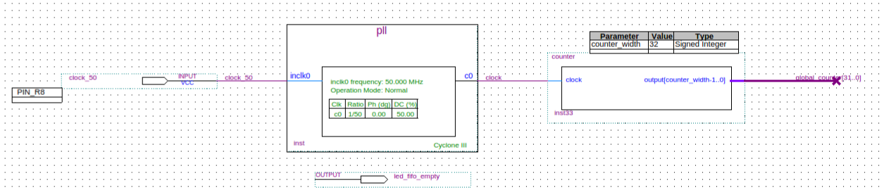
Then we feed the sensor signals to one of these lighthouse modules
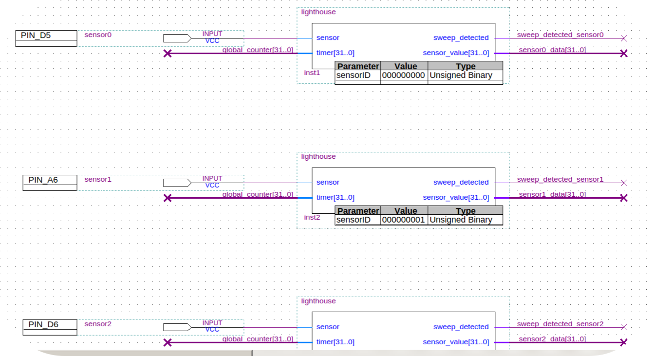
The spi module looks like this
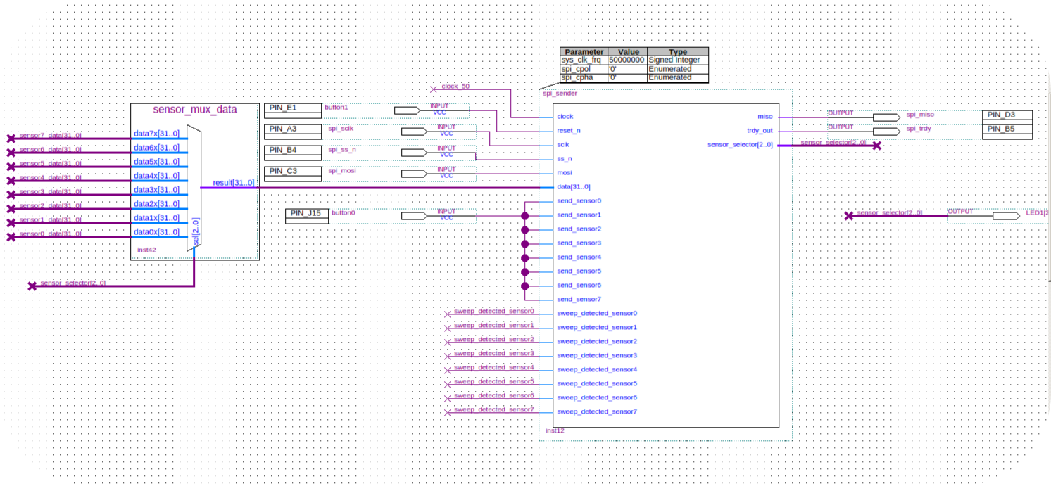
2. Transmitting the sensor signals via SPI
[Note: This is the old data format. New data format is described in section 7.]
The MKR acts a the SPI Master. Whenever there is new data available (ie when the fpga decoded a valid sweep), it notifies the MKR via an extra pin. The MKR then starts downloading a 32 bitfield, which encodes the data in the following way:
- bits 31 - 13: sweep duration (in micro seconds)
- bit 12: valid sweep
- bit 11: data
- bit 10: rotor
- bit 9: ligthhouse
- bits 8-0: sensor id
3. Transmitting the 32-bitfield via UDP
The host listens to UDP broadcast messages. We are using google protobuffer for the custom messages. When the host receives a trackedObjectConfig message, it opens sockets for the sensor and logging messages and sends the respective ports via a commandConfig message to the MKR. The MKR is waiting for this message and once received, starts sending the sensor values augmented with a milliseconds timestamp.
This sort of infrastructure is very convenient once you start using many tracked objects. You just turn the thing on and the tracking is initiated. We implemented a yaml reader, which saves and reads information about an object (eg the relative sensor locations on the object, or a mesh to be used with it...).
4. Triangulation...
Read more »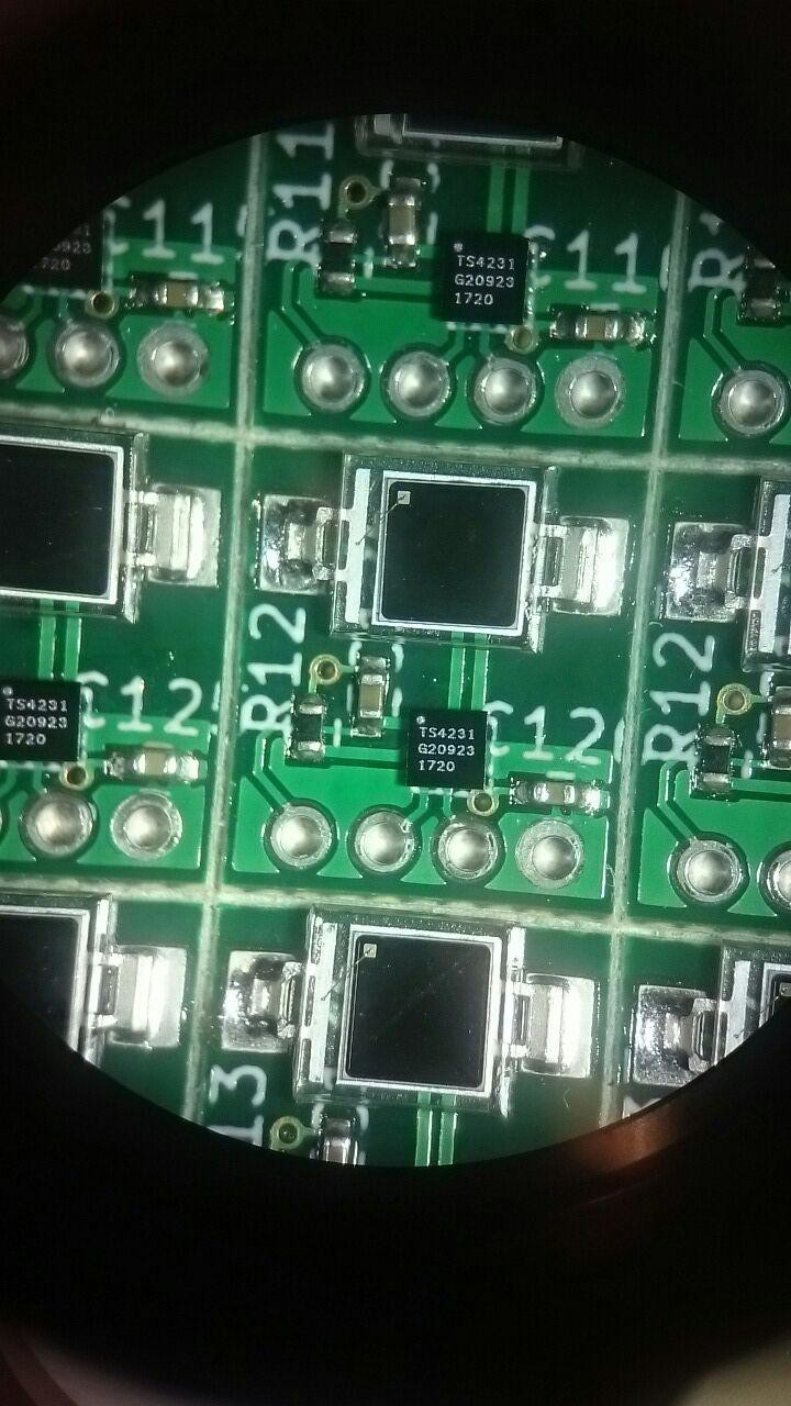


 tiefpunkt
 ElectroBoy
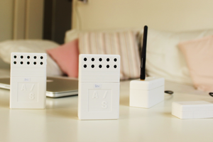
 Mario Frei
Excellent work!